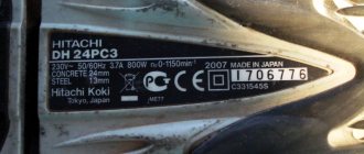
Repair instructions for the gearbox of rotary hammers P710 Interskol, BPR 241 SPARKY , P1-750-RE, P2-850-RE Fiolent
Disassembly
Remove in sequence: - special ring 1, - release sleeve 2, - ring 3, - ball 4, - spring 5. Pull the bearing shield out of housing 8 by 3-4 mm, remove switch 28a. Remove the bearing shield from the housing. Remove in sequence: - clamp 31, - spring 30, - ring 29. Remove closing spring 22.
Remove in sequence: - spring 21, - locking bar 20, - front switching bar 17, - rear switching bar 18, - spring 19 from the axle.
Remove washers 10, 16 and 55, spindle assembly and intermediate shaft 50 from bearing shield 24. Remove washer 43 and springs 42. Remove bearing 51. Remove gasket 26. If necessary, remove from bearing shield 24: bearing 23, bearing 52. Note: Washer 10 serves to ensure mounting distances and may be missing on some machines.
Remove ring 11, washers 12, spring 13 and gear wheel 14. Remove cylinder 40 with piston 38. Remove piston 38 from cylinder 40. Remove ring 37 from spindle 15. Remove sequentially: - catch sleeve 35, - rubber washer 34, - impact intermediate body 33. If necessary, remove rings 32, 36, 39. Remove axle 41 and washers 27.
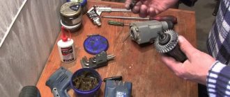
Remove, in sequence, the intermediate shaft gear 44 and the switching bushings 45 and 46. Remove the large intermediate gear 49 and the swing bearing 48 from the intermediate shaft 47. Tools: rack press, gasket, mandrel.
Apply grease 5 to the intermediate shaft 47 in an amount of about 1 g. Press in successively the swing bearing 48 and the large intermediate gear 49. Assemble in sequence the switching bushing 46 and the gear wheel of the intermediate shaft 45. Tools: rack press, bushing (pipe) with inner diameter 8 mm.
1. Apply grease to the cylinder bore 40. 2. Assemble washers 27 and axle 41. 3. Insert ring 39 into piston bore 38. 4. Apply grease to the cylinder bore and to the piston. 5. Insert piston 38 into cylinder 40.
1. Install rings 32 on the intermediate striker 33. 2. Insert ring 36 into the channel of the clamping sleeve 35. 3. Place in sequence: - spindle gear wheel 14, - spring 13, - washers 12, - ring 11 on spindle 15. Into the spindle in series insert: - intermediate striker 33, - rubber washer 34, - clamping sleeve 35, - ring 37. Note: Clamping sleeve 35 is inserted with a large chamfer into ring 37. Tools: rack press, pliers and mandrel for pressing ring 37, sleeve for pressing ring eleven
Install the intermediate switch bar 18 on the switch bar 17 and the spring 19 so that the spring is between the intermediate switch bar 18 and the switch bar 17, as shown in the figure. On axis 53 install sequentially: - spring 21, - locking bar 20, - switching bar 17 together with intermediate switching bar 18 and spring 19.
Install bearing 23 and bearing 52 on bearing shield 24. Install the spindle assembly on the bearing shield and measure the mounting clearance. With a gap of 92.38. 92.7 install washer pos. 10. With a gap of 92.7. 93.32 - washer pos. 10 is not installed.
Insert the cylinder with piston 40 into the bearing assembly shield 54.
Install the bearing assembly 51 on the intermediate shaft 50. Assemble the bearing shield 54, the intermediate shaft assembly and the bearing assembly 51 so that the thrust bearing axis fits into the hole of the cylinder axis, as shown in the figure.
Place gasket 26 on the bearing shield. Install the switching mechanism SW on the bearing shield so that the fork of the switching bar fits into the channel of the switching sleeve. Assemble washers 55 and 16 and spindle assembly SP in sequence. Note: Rotate the switching sleeve so that its cams are in contact with the end surface without entering the channels of the thrust bearing 48.
Assemble: - washer 10 (if necessary, see point 10), - washer 43, - springs 42. Place locking spring 22 on the bearing shield.
On switch 28 install: - ring 29, - spring 30, - lock 31.
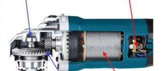
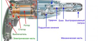
Interskol hammer drill design
The tool can operate in three modes: drilling, impact and drilling with impact. The SDS plus chuck helps you quickly change attachments for work. The safety clutch can prevent tool breakage if the drill gets stuck in the material.
The hammer drill has one speed and rotation speed adjustment. Additional features of the tool include an additional handle, a depth limiter and a power button lock.
All rotary hammers of the company are assembled according to the same scheme. There are three main blocks: impact reducer block, power supply, stator block.
These mechanisms have their own characteristics for different groups of instruments.
Operating principle and modes
The hammer drill operates in three main modes:
- Impact with rotation - makes it possible to drill through a hard and thick surface without much effort.
- Impact without rotation - allows you to hit concrete surfaces.
- Rotation without impact - turns the hammer into a drill.
Important! If you choose the right mode, the tool can be used in the process of gating for wiring. The result will be far from ideal, but all defects will be hidden by subsequent treatment of the walls.
The operating principle of the device is simple:
- Current passes through the electric motor, starting the remaining parts of the mechanism.
- The stator shaft begins to rotate due to its location on bearings. At its end there is a helical gear, which reduces the speed and increases the torque.
- Due to the rotation of the bearing, an impact option occurs.
This causes all the parts inside the hammer to move and interact with each other, transferring energy to the gear, which regulates the power and operation of the hammer.
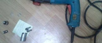
Disassembling the hammer drill
Let's start with the keyless chuck. The disassembly process consists of the following points:
- Removing a special ring
- Removing the release sleeve
- Eating another special ring and ball
- Removing the Coil Spring
In order to remove the gear housing, you first need to remove the mode shift knob.
Then the barrel, firing pins and firing pins are disassembled. The intermediate shaft is disassembled in the order of the following parts. The electrical part consists of three blocks - a rotor, a stator and a control circuit with carbon brushes. All blocks are disassembled in detail. After this, the hammer drill can be considered completely disassembled.
Do-it-yourself hammer drill repair
The tool can only be repaired after the allotted warranty period has expired. Mechanical damage is much more difficult to fix than problems with the electronic unit. Establishing the cause of a breakdown takes time - you need to inspect all the mechanisms. After this, you can fix the problem.
If the device turns on, but does not perform the chiselling function, then the breakdown may lie in the operating mode switch. Worn switch fingers may indicate a problem. Wear occurs due to constant contact with rotating mechanisms.
Disassembling Interskol rotary hammers models P18, P22, P26, P28, P30, P600, P710
The operating principle of all rotary hammers is the same.
The rotational moment from the rotor is transmitted to the barrel shaft and the working tool attached to it. At the same time, with the help of a swinging bearing, popularly called a “drunk bearing”, the torque is converted into a reciprocating motion, transmitting the shock impulse to the working tool.
All Interskol rotary hammers are assembled according to one general scheme and consist of the same blocks.
Conventionally, Interskol rotary hammers consist of three blocks:
- Impact unit gearbox unit.
- Stator block.
- Power and control circuit block.
Repair of Interskol rotary hammers should begin with studying the tool diagram, preparing the tools and the workplace.
The indicated blocks for the listed models have their own design features.
For ease of consideration, we will divide the presented rotary hammers into groups.
- In the first group we will include Interskol P-18, P-22, P-24, P-26, P-30 rotary hammers.
- In the second group, we will consider disassembling the Interskol P-600 and P710 hammer drills.
Electrical Diagram of Drill
If the light comes on, everything is fine with the button, but if you notice a malfunction, it’s time to replace the button.
The simplest diagram, and best demonstrating the principle of operation, is the following. That's all, in conclusion I can say that the method I told you works very well, I have tested it myself more than once.
If the light comes on, then everything is fine with the button, but if not, then the easiest way to fix the problem is to replace it. What's inside Drill repair. This happens very often, do it yourself
If the light comes on, everything is fine with the button, but if you notice a malfunction, it’s time to replace the button. In this case, repairs must be carried out using specialized tools.
More scientifically it looks like this. Since gearbox failure is the most common mechanical failure, we will dwell on its design in more detail.
The most simplified of all the diagrams and the one that best shows the principle of operation is shown in Fig. We connect the device to the contacts on the plug, but the device does not respond, because the start button is not in the working position.
I hope this helps, the drill is good. If metal parts break, it is better to purchase a new unit.
The drill does not turn on, do it yourself REPAIR.
Design features of the SDS-plus type keyless chuck
Let's start with the differences in the design of the quick-release chuck mounting assembly.
The principle of disassembling keyless chucks is almost the same for all rotary hammers.
Interskol hammer drills use a quick-release chuck of the SDS-plus type. To work with an Interskol hammer drill, you must use a tool with an SDS-plus shank.
Disassembling the keyless chuck
Let's look at disassembling the keyless chuck using the example of the Interskol P-26/800ER hammer drill.
Having installed the hammer drill on the back of the handle, you need to remove the protective sleeve pos. 1, remove the washer pos. 2 and remove the locking ring pos. 3.
Next, remove the washer pos. 4 and the retaining ring pos. 5. At the next stage, the pressure sleeve pos. 6 is removed.
To release the fixing ball pos. 8, you must press the special washer pos. 9. Take out the ball, take out the conical spring pos. 10.
The design of the quick-release chuck for the Interskol P-30/900ER hammer drill contains fewer parts. But the disassembly procedure remains the same.
The quick-release chucks for the Interskol P-600ER and P-710ER rotary hammers are almost identical and are disassembled in an identical sequence.
Keyless chuck for rotary hammer Intersol P-30/900ER
The parts of the quick-release chuck for Interskol P600ER and P710ER rotary hammers are dismantled in the following sequence:
- the special ring pos. 1 is removed;
- release sleeve position 2 is released;
- press the special ring pos. 3 and take out the ball pos. 4;
- the spiral spring pos. 5 is removed.
For all Interskol rotary hammers, to remove the gear housing, you must first remove the mode switch.
Dismantling the mode switching handle in the Interskol P-26 hammer drill
Having tilted the hammer drill to one side, turn the mode knob pos. 28 counterclockwise until it stops while pressing the button pos. 26. Remove the handle from the hammer drill body.
Never switch the mode knob while the hammer drill is running.
Dismantling the intermediate shaft
To disassemble the intermediate shaft pos. 57, you need to remove it from the inner housing. From the shaft pos. 58, remove the switch arm pos. 55 and the spring pos. 56.
On the other side: remove the support bushing pos. 65, the spring support pos. 64, the spring pos. 63, the combined gear wheel pos. 62.
Intermediate shaft of the Interskol P-26/800ER rotary hammer Catalog of spare parts for the intermediate shaft of the Interskol P-26/800ER rotary hammer
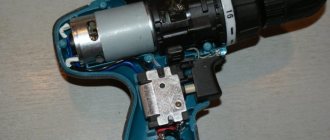
Disassembling the impact mechanism of the Interskol P710ER hammer drill
The design of the impact mechanism and the disassembly procedure for the Interskol 710ER rotary hammer are somewhat different from rotary hammers of other models.
The main differences are in the design of the intermediate shaft, the hammer barrel and the mode switch.
Diagram of the impact mechanism and intermediate shaft of the Interskol P710ER hammer drill
The Interskol 710ER hammer drill is a rotary-impact machine. Consists of an electric drive and an actuator. A commutator motor is used as an electric drive. The actuator is a combination of a compression-vacuum type impact mechanism and a rotary mechanism. The reciprocating motion is transmitted by a rolling bearing.
The diagram shows the procedure for disassembling the barrel, position 15 (indicated by a red arrow), the composition of the strikers and strikers (indicated by a blue arrow). The green arrow indicates the details of the mode switch.
The intermediate shaft consists of a shaft pos. 47 and parts mounted on it. It is easy to disassemble, according to the attached diagram, and does not require special knowledge.
Disassembling the electrical part of the Interskol hammer drill
The electrical part of the Interskol rotary hammer consists of three main parts:
- rotor;
- stator;
- control circuits with carbon brushes.
The procedure for disassembling the electrical part of all models of Interskol rotary hammers is almost the same.
Electrical diagram of the hammer drill Interskol P-26/800ER
In the previous steps, we divided the housing into two: the gearbox housing and the stator housing.
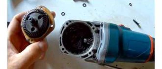
Stator disassembly
To disassemble the stator pos. 74, it is necessary to remove the protective diaphragm pos. 72 from the housing pos. 77, which covers the stator from dirt and dust.
Unscrew the two screws pos. 73 and pull out the stator pos. 74. To make the removal process easier, simply tap the end of the stator cover with a wooden hammer or block.
Terminal blocks pos. 75 can be removed from the stator. This is done in order to check the quality of the contacts from the stator to the brush holder.
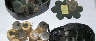
Disassembling the rotor
The rotor is disassembled when it is necessary to replace the commutator, bearings, or rewind the windings.
You can separate the rotor from the impact mechanism assembly by releasing two screws, pos. 68, and removing the shield, pos. 67.
From the rotor, pos. 69, it is necessary to remove the bearings, pos. 66, 70, and the damping bushing, pos. 71. The bearings are easily removed using a puller.
Disassembling control circuits and dismantling carbon brushes
The basis for controlling the Interskol rotary hammer is the switch pos. 87 and the reverse lock pos. 90. Using the combination button, you can set the rotary hammer speed of the electric motor.
To get the brushes pos. 83, you need to remove the brush holder pos. 81. It is removed by turning it counterclockwise by 90º. Having released the brush holder, the carbon brushes are easy to remove.
The design of the Interskol P710ER and P600ER rotary hammers has its own characteristics:
- there is no combined brush holder;
- a different type of switch was used.
All! The Interskol hammer drill has been disassembled. Read the repair instructions and how to assemble and lubricate the hammer drill.
Disassembly and assembly of gearbox P710
Instructions for repairing the reduction gear of rotary hammers P710 Interskol , BPR 241 SPARKY, P1-750-RE, P2-850-RE Fiolent
Remove in sequence: - special ring 1, - release sleeve 2, - ring 3, - ball 4, - spring 5. Pull the bearing shield out of housing 8 by 3-4 mm, remove switch 28a. Remove the bearing shield from the housing. Remove in sequence: - clamp 31, - spring 30, - ring 29. Remove closing spring 22.
Remove in sequence: - spring 21, - locking bar 20, - front switching bar 17, - rear switching bar 18, - spring 19 from the axle.
Remove washers 10, 16 and 55, spindle assembly and intermediate shaft 50 from bearing shield 24. Remove washer 43 and springs 42. Remove bearing 51. Remove gasket 26. If necessary, remove from bearing shield 24: bearing 23, bearing 52. Note: Washer 10 serves to ensure mounting distances and may be missing on some machines.
Remove ring 11, washers 12, spring 13 and gear wheel 14. Remove cylinder 40 with piston 38. Remove piston 38 from cylinder 40. Remove ring 37 from spindle 15. Remove sequentially: - catch sleeve 35, - rubber washer 34, - impact intermediate body 33. If necessary, remove rings 32, 36, 39. Remove axle 41 and washers 27.
Remove, in sequence, the intermediate shaft gear 44 and the switching bushings 45 and 46. Remove the large intermediate gear 49 and the swing bearing 48 from the intermediate shaft 47. Tools: rack press, gasket, mandrel.
Apply grease 5 to the intermediate shaft 47 in an amount of about 1 g. Press in successively the swing bearing 48 and the large intermediate gear 49. Assemble in sequence the switching bushing 46 and the gear wheel of the intermediate shaft 45. Tools: rack press, bushing (pipe) with inner diameter 8 mm.
Apply grease to the cylinder bore 40. 2. Assemble washers 27 and axle 41. 3. Insert ring 39 into piston bore 38. 4. Apply grease to the cylinder bore and to the piston. 5. Insert piston 38 into cylinder 40.
Install rings 32 on the intermediate striker 33. 2. Insert ring 36 into the channel of the clamping sleeve 35. 3. Place sequentially: - spindle gear wheel 14, - spring 13, - washers 12, - ring 11 on spindle 15. Insert sequentially into the spindle: - intermediate striker 33, - rubber washer 34, - clamping sleeve 35, - ring 37. Note: Clamping sleeve 35 is inserted with a large chamfer into ring 37. Tools: rack press, pliers and mandrel for pressing the ring 37, sleeve for pressing the ring 11
Install the intermediate switch bar 18 on the switch bar 17 and the spring 19 so that the spring is between the intermediate switch bar 18 and the switch bar 17, as shown in the figure. On axis 53 install sequentially: - spring 21, - locking bar 20, - switching bar 17 together with intermediate switching bar 18 and spring 19.
Install bearing 23 and bearing 52 on bearing shield 24. Install the spindle assembly on the bearing shield and measure the mounting clearance. With a gap of 92.38. 92.7 install washer pos. 10. With a gap of 92.7. 93.32 - washer pos. 10 is not installed.
Insert the cylinder with piston 40 into the bearing assembly shield 54.
Install the bearing assembly 51 on the intermediate shaft 50. Assemble the bearing shield 54, the intermediate shaft assembly and the bearing assembly 51 so that the thrust bearing axis fits into the hole of the cylinder axis, as shown in the figure.
Place gasket 26 on the bearing shield. Install the switching mechanism SW on the bearing shield so that the fork of the switching bar fits into the channel of the switching sleeve. Assemble washers 55 and 16 and spindle assembly SP in sequence. Note: Rotate the switching sleeve so that its cams are in contact with the end surface without entering the channels of the thrust bearing 48.
Assemble: - washer 10 (if necessary, see point 10), - washer 43, - springs 42. Place locking spring 22 on the bearing shield.
On switch 28 install: - ring 29, - spring 30, - lock 31.
Install the gearbox on the shield, leaving a distance of 3-5 mm before final closing. Install switch 28 on the gearbox so that the pin fits into the slot of the intermediate switch strip. Smoothly turn switch 28 to the “impact drilling” position, while simultaneously pressing the gearbox until the gearbox is completely closed. Insert spring 5 and ball 4 into the spindle. Apply grease 3 to ring 3 and insert into release sleeve 2. Insert release sleeve into the spindle.
READ How to Drill a Hole in Concrete Without a Hammer
Operating mode switch The switch should move easily, without tightening, and the end positions should be clearly fixed.
Initial position for gearbox assembly The gearbox is installed in a vertical position. Mutual arrangement of parts and assemblies: - centering bushings 9 are installed in the shield, - pins of the rear shifting bushing 46 are not engaged with the swing bearing, - the fork of the rear shifting bar 18 is engaged in the channel of the rear shifting bushing 46, - the fork of the front shifting bar 17 is engaged in the channel of the bushing front shifting bar 45, - the gear wheel of the intermediate shaft 44 is engaged in the front shifting bushing 45. The free movement of the front shifting bar 17 and through it the front shifting bushing 45 is checked - through several compressions and releases of the spring 19.
Assembling the gearbox with the housing The closing spring 22 is pressed into the inside of the gearbox and the gearbox housing kit 8 is installed on the gearbox. In this case, it is necessary to orient the spindle kit so that it fits into the needle bearing in the housing. The gearbox housing 8 is held with one hand so as not to allow it to completely close the gearbox; a stroke of 4-5 mm remains. In this case, it should be in the following position: - through the hole for the switch, the channel formed by the front and rear switching strips should be visible; — the fork of the closing spring 22 must coincide (without going in) with the hole for the switch.
Final assembly of the gearbox - switch 28 is mounted in the hole of the gearbox housing 8 in the position indicating the “drilling with impact” mode, - the switch is turned clockwise to the “hammer” mode, - pressing and orienting the housing down to the shield, close the gearbox completely so that the position the end of the bearing shield is aligned with the end (edge) of the housing. At this moment, the centering bushings, the intermediate shaft and the axis of the mode switching unit enter simultaneously into the corresponding slots of the gearbox housing and, perhaps, the housing is not immediately fully installed. To simplify the final closing, it is necessary to turn the switch several times from the “hammer” mode position to the “impact drilling” mode position. - after installing the gearbox housing in its final position, it is necessary to check the inclusion in the “drilling” mode; if this switching is carried out easily and without problems, then the final assembly of the gearbox was successful. After this check, the switch is set to the “impact drilling” mode position. They are connected in series to the spindle: ball 4, spring 5, sleeve 3, release sleeve 2 and ring 1.
Recommended lubricants for rotary hammer repairs
Manufacturer designation
Operating temperature, o C
At pos.36, place the barrel on the gear pos.35, on the other hand, the cam bushing pos.38 and the camshaft bushing connection, attach the needle rollers pos.37 and the retaining ring pos.34.
The gear is pressed by the spring pos. 33, washer pos. 32 rests on the barrel, and everything is secured with a locking ring pos. 31.
The trunk is inserted into the body pos. 18, in which the cuff pos. 19 pre-inserted roller bearing pos. 20 and sleeve pos. 21 is pressed.
Barrel, attacker, hunter before assembly
The barrel assembly is completed by installing the firing pin inside and gripping it after lubricating the internal surfaces. The hunter's installation in the barrel is secured with a locking ring.
Piston Assembly Poses 47 Start by installing pos. 48 and two rings pos. 49. The finger acts as a lever to support the rolling stock. 60. Hairpin village. 45 with pre-installed sealing ring pos. 46 is inserted into the piston.
Before inserting the hammer into the piston, the inside surface of the piston should be checked for roughness. There should be no scratches on the surface.
After lubricating the inner surface of the piston with a thin layer of Cyatim-221, insert the hammer inside.
In the design of the Interskol P-26 / 800ER rotary hammer, the working tool is inserted into a special tool receiver and secured in a chuck.
Details of the chuck without key and tool of the Interskol P-26 / 800ER hammer drill
Item Tool Receiver Assembly. 12 is simple.
An industrial array of pos. is assembled in the internal part of the receiver. 16 inserted. For industrial weights, you must first put on the sleeve pos. 15, cuffs pos. 14, rubber ring pos. 13. Before assembly, be sure to lubricate the rubber O-ring and the inside of the receiver with Qiatim-221 lubricant.
The assembled tool receiver is inserted into the barrel barrel. 36. Intermediate shaft assembly
In Interskol P-26/800ER the intermediate shaft is a complex assembly.
First, assemble the components of the rolling bearing according to option 60. Needle bearing pos. 61 and combined gear pos. 62 are inserted into the bearing.
Washing Interskol P-26/800ER punch parts before assembly
Assembling the P 710ER rotary hammer
The assembled unit is inserted into the body, pos. 53 with simultaneous installation of the piston pos. 47. Before installation, the roller bearing shells are inserted into the pin. 48.
The shaft of the installed gearbox is secured with a bracket pos. 50.
Installing Retaining Bracket Assembly
At the next stage, the shaft of gears pos. 58 is installed in the intermediate shaft with output pos. Put this on.
The assembled unit is lubricated with transmission oil.
It remains to place the barrel pos. 36 on the pistons.
Lubricate the gearboxes with the recommended lubricant and close the outer gearbox cover. 18.
With the strike vertically mounted in a vise, assemble the chuck without a key. After lubricating the internal cavity of the barrel, insert the receiver of the device.
Align the holes of the tool receiver and the cylinder, then insert the rollers into position. 11 in them.
Place the conical spring pos. 10 on top, a special washer pos. 9 and insert the ball pos. 8.
Assembly of the Interskol P 710er Hammer
- the Interskol drilling rig assembly process
- Lubricant selection
- Assembling the impact block
- Tool Receiver Assembly
- Intermediate node
- Impact assembly
- SDS keyless installation
- Setting the Mode Knob
- Stator assembly
- Interskol P-26 / 800ER hammer drill assembly
- Video assembly stamps Interskol
- INTERSKOL P-18 / 450ER rotary hammer assembly
- INTERSKOL P-22 / 600ER rotary hammer assembly
- INTERSKOL P-26 / 800ER hammer drill assembly
- Interskol P-600ER rotary hammer assembly
- INTERSKOL P-710ER hammer assembly
READ Which drill stand to choose?
Hammers are quite easy to maintain. To maintain the working condition of the Interskol punch, it is necessary to promptly change the gearbox lubricant every time you replace worn motor carbon brushes.
Old grease must be removed without fail, preferably using special detergents used in service centers. But the homeowner copes well with kerosene and gasoline. Self-installation of Interskol drill bit. it's a simple process. You just need to read the disassembly instructions, diagram, spare parts catalog. Before assembly, prepare new or repaired and cleaned parts, a new seal repair kit, lubricants, tools and accessories. Do not forget about proper preparation of the workplace and its lighting.
The new lubricant fills the cleaned parts and only those that are recommended for this block.
Apply new lubricant, do not overdo it: excess grease during hammer operation is often squeezed out through the gear housing and leads to destruction of the seals.
Before assembling the parts, check the internal surfaces for roughness. The surface must be polished to a mirror finish. At low roughness, abrasion of rubber seals occurs more intensely. Read more about repairing an inter-skor drill.
the Interskol drilling rig assembly process
The assembly of interspeed drills can be divided into several stages:
- Installation of rubber seals.
- Assembly of individual units.
- Mounting blocks.
- Assembling the electrical part.
- Checking the functionality of the power tool.
All Interskol seeders consist of several large blocks:
- Mechanical shock assembly unit.
- Intermediate shaft block.
- Transmission.
- Stator block.
- Block control unit.
To lubricate rotary hammers, domestic manufacturers have developed special lubricants. The lubricant is divided in accordance with the operating conditions of the units. To lubricate the gearbox, rolling bearings and clutch, it is recommended to use lubricants specifically designed for these units.
Typically, oils are divided into three categories:
Unraveling the rotary hammer P 710ER
- For particularly loaded units, such as impact mechanisms, gearboxes, gear shafts.
- For lubricating the drill shank.
- For lubricating rubber seals.
- For particularly loaded components, such as the impact mechanism, gearbox, intermediate shaft.
- For lubrication of drill shanks.
- For lubricating rubber O-rings.
It is recommended to use Qiatim-221, which does not attack rubber, as a lubricant for rubber seals.
Interskol well gearboxes .
Before installing rubber seals on a workpiece, they should always be lubricated with an inert lubricant that can withstand temperatures up to 120°C.
It is recommended not only to use fatty inert rubber, but also to ensure high tightness during operation. For domestic lubricants, look for Tsiatim-221.
Household lubricant for sealing rubber rings in hammer drills
To securely grip the tool and easily pull it out at the end of work, it is recommended to use a special shaft shank.
For Interskol rotary hammers, the impact block consists of a cylinder and parts of the impact mechanism.
Let's look at the assembly of the striking element using the Interskol 26/800ER barrel as an example.
The impact mechanism consists of an industrial mass of pos. 16, barrel pos. 37, attacker pos. 45 and piston pos. 47.
The shock impulse is created by the reciprocating motion of the piston postures. 47 in barrel pos. 36. Intruder village. 45 moves inside the piston and gives impulse to the industrial mass pos. 16. But the industrial mass already transmits the shock impulse to the instrument device pos. 12. In this circuit there is another device that smoothes the magnitude of the shock pulse from the striker to the industrial mass. The device is called an intruder, pos. 42.
Barrel assembly
The gear pos. 35 is put on the barrel pos. 36, on the other side the cam bushing pos. 38 and the gear-cam bushing connection is fixed with needle rollers pos. 37 and a retaining ring pos. 34.
The gear is pressed by a spring, pos. 33, a washer, pos. 32, is put on the barrel, and everything is secured with a retaining ring, pos. 31.
The barrel is inserted into the body, pos. 18, into which the cuff, pos. 19, is first inserted, the roller bearing, pos. 20, and the bushing, pos. 21, are pressed in.
Barrel, firing pin, catcher before assembly
The barrel assembly ends with the installation of the firing pin and catcher inside after lubricating the internal surfaces. The installation of the catcher in the barrel body is secured with a locking ring.
Selection of lubricants
Domestic manufacturers have developed special lubricants for lubricating hammer drills. The lubricant is divided according to the operating conditions of the units. To lubricate gearboxes, rolling bearings and clutches, it is recommended to use lubricants specially designed for these components.
Conventionally, lubricants are divided into three categories:
It is advisable to use Tsiatim-221 as a lubricant for rubber sealing rings, which does not destroy rubber.
Special lubricants are used for gearboxes of Interskol rotary hammers.
Domestic lubricant for rotary hammer gearboxes
Before installing rubber sealing rings on parts, they must be lubricated with a lubricant inert for rubber that can withstand temperatures up to 120 ºC.
It is recommended to use not only a lubricant that is inert for rubber, but also one that provides high sealing during operation. Among domestic lubricants, pay attention to Tsiatim-221.
Domestic lubricant for rubber sealing rings in rotary hammers
To securely grip the tool and easily remove it at the end of the work, it is recommended to use a special bundle for shanks.
Domestic lubricant for rotary hammer drills