This went on for a long time until, in 1907, Canadian inventor Peter Robertson patented the Robertson screw with a standard square hole into which the tip of a screwdriver was inserted. Since that time, screws began to be produced on an industrial scale and used in households. Later, in 1934, inventor Henry Phillips modified the screw head and a screw with a Phillips notch appeared, into which a corresponding screwdriver was inserted. By that time, the engine had already been invented and the idea of creating a “rotator of screws and screws” was in the air. However, there were big problems with the batteries - their weight and dimensions. The problem was solved only in the 1980s, when the first nickel-cadmium Ni-Cd and lithium-ion Li-Ion batteries appeared.
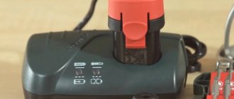
The USA and Japan were the first to master the production of household and professional products. All this happened thanks to the advent of new energy-intensive electricity batteries. We will urgently change them inside the Interskol DA-10/10.8 ER cordless drill-driver that fell into my hands. The malfunction was this: when the button was pressed, the engine simply did not spin, but the LED lighted up , although the light was weak.
How to disassemble an Interskol screwdriver
The tool includes many working elements. Among the most important are the following:
- Electric motor. The electric motor includes brass bushings and a steel armature. Several turns of winding and a gear are attached to the armature. At the bottom of the armature there are graphite brushes, through the use of which current is transmitted to the collector.
- Gearbox. Designed to transmit rotation using mechanical transmission. Can be presented in the form of a 1 or 2 stage gearbox. As a rule, screwdrivers use 2-stage gearboxes. You can repair the Interskol screwdriver gearbox yourself, taking into account the recommendations of experienced craftsmen.
- Accumulator battery. Consists of several small batteries. They are connected in series. Different models may have different compositions, which affects the power and duration of operation without intermediate charging. In order to extend the life of the battery, it must be charged correctly, which depends on the composition of the element. Experts recommend that after purchase, perform 3 full battery charging cycles, each of which is performed after the battery is completely discharged.
- Cartridge. Screwdrivers use quick-release chucks. It can be attached in several ways (threaded, screw, Morse taper). This indicator determines the quality of the tool attachment clamp and the method of its dismantling.
Before starting any repairs, it is necessary to carry out an operation such as disassembling the Interskol screwdriver. To do this, it is recommended to follow the following sequence of actions:
- Disconnect the battery.
- Separate the cartridge, spring and rotary housing. In this case, you should pay attention so that the balls do not roll out.
- Unscrew the bolts connecting the 2 halves of the housing (they are located around the perimeter of the housing).
- Carefully remove all elements located inside the housing.
- Disable the start button.
- Remove the speed switch and adjustment clutch.
- Remove the electric motor.
Only after this will it be possible to repair any part of the screwdriver.
How to repair a cartridge
The chuck for each specific screwdriver model differs from similar elements of other models. The main distinguishing feature is the method of mounting the cartridge:
- Morse cone.
- Threaded connection.
- Threaded connection with fixing screws.
To determine the mounting method, it is best to use the markings that are applied to the cartridge case:
- The marking value “1–6 B10” indicates the method of fastening using a Morse taper.
- an inscription like “1.0–11 M12x1.2” or “2–13 mm ½-20 UNF” indicates a metric or inch thread.
If the cartridge is attached by means of a thread, then it is necessary to perform the following steps:
- Unclench each jaw of the chuck.
- If there is a screw, remove it.
- Clamp the L-shaped hex key (10 mm) with the short side into the chuck.
- Start and immediately turn off the screwdriver at low speeds, so that the long edge of the hex key hits the table. In order not to turn on the device, you just need to hit the hexagon with a hammer several times. This will cause the thread to shift and the cartridge to unscrew.
If there is no result, you can disassemble the screwdriver and remove the assembled gearbox from it. To do this, it is enough to use an L-shaped tubular wrench (often “19”) to unscrew the cartridge, clamping the gearbox mounting bolt with the socket heads of the keys on the other side. They provide the necessary support, making the cartridges easy to unscrew by hand.
When disassembling the cartridge, the plug at the base is removed. The plastic plugs must be carefully pryed off with a knife. Metal ones should be knocked out with a hammer, striking the base of the cartridge:
- It is necessary to provide in advance the presence of a large bolt, which should be secured in the chuck and pressed with light effort to perform alignment. The protrusion of the bolt head should be more than 2-3 cm above the chuck.
- Next, hit the surface of the bolt head with a hammer. The cartridge should pop out of the holder.
The most common cartridge malfunction:
- bits are not clamped evenly;
- backlash occurs between the bit and the cam;
- The cam extends unevenly.
To find out the causes and eliminate them, you need to perform the following steps:
- Disassemble the cartridge.
- Remove the cone nut, which consists of two elements.
- Unscrew the clamping jaw.
- Check the threads on the nut and cam and replace any defective parts.
- Completely assemble the cartridge.
It is worth considering that it is quite difficult to purchase a cam or a cone nut, since they are supplied to the market as a complete set. But they can be removed from other similar cartridges. In this regard, it is best to replace faulty cartridges with new ones. When purchasing a new element, it is recommended to go to the store with a screwdriver and a dismantled old chuck.
How does a screwdriver work? + (Video)
What problems can be fixed at home? How to recognize this or that breakdown? To give specific answers to the questions asked, let's first understand the internal mechanism of the tool. The main protruding element is the power button. It is used to start the device and to change the speed and direction of rotation of the working part - the chuck.
The speed is adjusted using an electronic device based on a transistor. The speed of rotation is directly proportional to the force of pressing the button. The reverse is started by replacing the polarity of the electric current at the terminals. Traditionally, a screwdriver is equipped with single-phase commutator-type motors that operate on continuous current. The engine includes a housing, magnets, an armature and brushes.
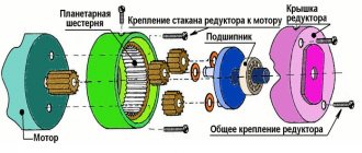
Rotation from the motor passes to the gearbox. Next, it converts high engine speeds into low cycles on the shaft, and a cartridge with active bits is fixed in it. The gearbox can be used classic, like on a conventional drill, and also planetary. Lately, the classic gearbox has hardly been used, so let’s not stop and move on. The planetary mechanism includes:
- Ring gear
- Sun gear mounted directly on the motor shaft
- Satellites
- two or three drivers
Next comes the force stabilizer, which has sixteen positions. These positions provide a specific tension on the self-tapping screw, so as not to spoil the material with which they are attached. The last component is the cartridge.
Self-repair: how to disassemble an Interskol screwdriver.
A screwdriver is a power tool that is used for loosening or tightening screws, bolts, screws, nuts, as well as for drilling holes in wood or metal. After many years of use, the Interskol screwdriver may break and will have to be repaired. Failures can be: • mechanical; • electric. What kind of damage can be repaired at home? How to recognize these problems? To answer this question you need at least a brief knowledge of the internal structure of the instrument.
The main cause of failure is the start button. It is designed to turn on, regulate the speed and switch the direction of rotation of the working body. Also, wear of the loaded parts of the planetary mechanism and the overrun clutch can cause failure. We’ll look at how to disassemble a screwdriver, identify faults and make repairs yourself in this article.
How to disassemble a screwdriver: cartridge, battery
Innovative technologies in construction are developing every day; it has long been no longer a secret that a screwdriver. An indispensable assistant for both the most experienced specialist and the novice master. Thanks to it, you can simply tighten various self-tapping screws when assembling furniture structures, as well as when repairing equipment and residential premises.
- How to remove a cartridge from a screwdriver
- How to revive a screwdriver battery
- Repair of box and screwdriver button
- How to change the chuck on a drill
The fact that some equipment breaks down over time is no longer news to us, so it becomes possible to disassemble a screwdriver and try to fix it yourself. But just without fanaticism, be careful when disassembling, especially such models as: Interskol and 12er 01, Interskol and 18er.
What does a screwdriver or tool design consist of?
When working with a screwdriver (popularly called a “shurik”), malfunctions arise that can be divided into repairable and non-repairable (requiring replacement). Non-repairable breakdowns, when a part cannot be repaired, include failure of the motor, button, gearbox, cartridge, etc., when they cannot be repaired, but can be replaced. Before repairing a screwdriver with your own hands, which any tool owner can handle, you need to understand its design features.
The main components of any cordless screwdriver include:
- Electric motor - driven by an autonomous battery (9V, 12V, 15V and 24V). Network devices operate from a 220V network, so they have a large power reserve and cost 2 times less than portable models
- A gearbox is a device that converts high engine speeds into lower speeds. Consists of a set of gears (usually made of plastic, but steel models are also available)
- Start button - the part responsible for supplying voltage to the motor shaft and moving the armature
- Battery or power cord. There are two types of batteries used in portable devices: nickel-cadmium and lithium-ion. If the device is networked, then its weight is much less, but at the same time, to use it, you need to connect the plug to the socket
- Force regulator - a device responsible for the amount of force applied to screws, holes made or polished surfaces
- Chucks are a mechanism in which attachments are secured to perform the corresponding actions. Screwdrivers usually use quick-release (keyless) chucks
- Reverse is another useful option that allows you to change the direction of rotation of the cartridge. This is convenient when installing and removing attachments into the device socket.
- The case is made of impact-resistant plastic, which is done not only to reduce the cost of the device, but also to increase safety when working with the tool.
This is interesting! Each unit has a corresponding purpose, however, the failure of these parts is affected not only by the frequency of use of the tool, but also by the correct use of the device. For example, a screwdriver cannot be used for drilling concrete, since it does not have an impact function. If you drill holes in the wall with the device, then such a device will not last long.
Charger for screwdriver Interskol
Hand tools with self-powered sources are developing quickly and successfully. One of the most important areas is the improvement of batteries and their maintenance. The key to long-term and high-quality operation of battery power supplies is the charger. Now there are many companies on the market that produce their own tools with independent power supply and units for charging them. One of the popular brands of hand tools is . Together with power supplies, chargers for the interskol screwdriver battery. We will look at the operation of the charger in this article. But first you need to understand the principle of the power supply.
Operating principle of the block
The principle of operation of a rechargeable battery is that when charging under the influence of an applied voltage, charged electrons from the anode are introduced into the active charge holding part - the cathode. After the active element is completely saturated with electrons, charging is completed. When a load is connected, the movement of electrons occurs in the reverse order, and a potential difference, or voltage, denoted by the Latin letter U V (Volt), is created on the electrodes. The number of charged electrons in the active layer of the cathode is determined as the battery capacity.
Capacity is one of the most important parameters, which directly gives the concept of power. The physical quantity is power, denoted P (Watt), which is determined by multiplying voltage by current. So, if on a 12V assembly the designation is 2 Ampere-hour (Ah), this means that a 12-volt battery can deliver 2 amperes for an hour at a stable voltage. The battery power is calculated using the formula P=I*U and will be equal to P=2*12=24W (A*h). But if the voltage changes to 18V, then the power is P (W). will be equal to 36 W.
Variety of battery assemblies
The power supply consists of single elementary parts of a standard size, assembled in series, parallel or in a mixed circuit. Currently, nickel-cadmium (Ni-Ca), nickel-metal hydride (Ni-MH) and lithium-ion (Li-ion) elemental sources are used. These batteries are assembled into a single unit; they can be round, square, or flat. Depending on the active component, each battery is manufactured with a voltage from 1.2 to 3.6V. To increase the voltage they are connected in series, to increase the capacity (power) in parallel, a mixed connection is also used. So, for example, to get a voltage of 12V, you need to connect 12 1V elements in series. And to double the power you need to connect these same elements in parallel.
First builds
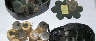
The very first assemblies were assembled from elementary batteries with a cadmium-nickel active component. Assemblies with (Ni – Ca) had a number of exceptional properties: they were not afraid of working in the cold; The charging cycle reached 300 cycles. The battery could be stored in working condition for many years. But, along with their advantages, they have a significant drawback - this is the “memory effect”, in other words, the assembly could not be left in a charged state because the active metal - cadmium, under the influence of charged electrons, oxidized, the battery decreased its original capacity. And, although the manufacturer’s passports contained recommendations for proper operation, many users did not follow them, as a result, the preparation of the battery for storage (the discharge after each operation should remain no more than 30-40%) was not carried out and the batteries did not last their warranty period.
Nickel–metal hydride batteries
The next step in the development of autonomous power sources was batteries with a nickel-metal hydride (Ni-MH) active component. Manufacturers positioned the product as devoid of the main drawback (Ca-Ni) “memory effect”. But, after application in practice, it turned out that the main disadvantage decreased slightly, and the new active layer acquired additional negative properties: it could not work at subzero temperatures, and the cost turned out to be much more expensive. Therefore, the production of these elements was very quickly abandoned, especially since a new active component, lithium-ion, was developed and offered to the market.
Lithium ion batteries
Lithium-ion (Li-ion) products turned out to be not too expensive, but compared to previous ones they acquired several significant advantages:
- discharge – charge cycle increased from 300 to 400;
- reduced self-discharge;
- The memory effect is almost completely eliminated.
- The full charge time has been reduced to one hour.
But it was still not possible to avoid undesirable properties - uncontrolled heating to high temperatures during overvoltage. If a slight overvoltage is possible in a device where batteries are used, an internal short circuit may occur in the elements and the active layer will become very hot. This was especially true for products with low 12V power. To reduce these disadvantages, I have developed chargers capable of analyzing not only the charging process, but also each element separately.
Attention! Separate chargers are required for each type of battery.
Charger design
The simplest circuit solution may be to connect the batteries of an Interskol 12 volt screwdriver for Ni – Ca batteries. The station is assembled from the most necessary elements for reducing, rectifying and stabilizing the current. Let's take a closer look at the operation of the elements. The secondary winding of the transformer is designed for a voltage of 15 - 17 V and a current of at least 5A. The reduced voltage at the output of the secondary winding is rectified by a diode assembly or a diode bridge assembled from individual diodes with a power of at least 1A. To smooth out ripples there is a 100 µF electrolytic capacitor. For indication, an LED is used, which is installed in the collector circuit of the transistor and opens when voltage is applied to the base through resistance R2 after the charging circuit is closed. The required voltage of 12V is provided by the zener diode VD1. This circuit ensures that the battery is fully charged in 4-5 hours.
Charging station diagram for Ca-Ni batteries 12V
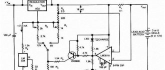
Improved charger circuit for interskol CDQ-F06K1 screwdriver
with charging current stabilization, developed on the HCF4060BE chip. The microcircuit is a 14-bit master oscillator with which the bipolar transistor S9012 is controlled. The transistor load is relay S3-12A. The introduction of a counter into the circuit allows the circuit to work as a timer that turns on the relay for a given time, thereby allowing you to set the charger modes of the Interskol 12V screwdriver.
Let's consider the operation of the circuit when connecting the JDQK1 relay to the network. The microcircuit receives power from a zener diode VD 6 12V - this zener diode sets the setting voltage to 12V, after which power is supplied to pin 16 of the microcircuit. After power is supplied to the microcircuit, current pulses arrive at the base of the S9012 transistor, opening it.
The transistor opens and the voltage flows to the contacts of the JDQK1 relay, the contacts of which close and the charging current flows to the charging unit. The VD5 valve is installed to protect the battery from reverse discharge if the mains power is turned off. The transformer is used in a circuit with a power of 25 - 30 W; after the secondary winding, a 5 A fuse is installed in front of the rectifier diode bridge. Such a circuit allows you to connect the network without worrying about disconnecting and monitoring the load. The red LED indicates charging, the green LED indicates charging has stopped.
Attention! Before installing Ca-Ni batteries at the station, it is necessary to discharge the battery to at least 70% of its full capacity.
Scheme of a universal station for 12V batteries
Interskol station for Ca-Ni assemblies 12V DA-10/12ER
This device is a small box with a slot for installing a battery. power supply from 220V network. The cord length is 2.5 m. There is a charging indicator. The approximate price of the product is 1000 rubles. There is no load resistor to discharge the battery to the required voltage (5 V). Weight 1.2 kg. There is a red indication - charging. Green indicates the battery is fully charged.
Features of Interskol charging blocks and troubleshooting
One of the distinctive features of Interskol charging units is the absence of a mains fuse and the use of a thermal fuse in the step-down transformer circuit. If it is difficult to find any malfunctions of electronic elements in the circuit, then one of the malfunctions associated with the thermal fuse can be eliminated on your own. We are talking about a step-down transformer. The fact is that instead of a mains fuse, a thermal fuse is installed at the input of the primary winding, which is set to a temperature of 130°C. If the heating temperature of the windings is higher, this device operates without recovery. That is, the transformer is not in working condition, since the 220V supply voltage is not supplied to the primary winding. The thermal fuse is located under a layer of cover paper insulation of the primary winding. To eliminate the malfunction, it is enough to remove this part by connecting the lead ends directly to the winding. To increase the reliability of the entire structure, it is recommended to install a classic mains fuse afterwards.
Attention! Thermal insulating varnish with which the windings are impregnated is allowed if the windings are heated to no more than 180°C. Charge multiple batteries no earlier than 30 minutes later.
Video on troubleshooting a temperature sensor.
Where to buy a charger for an inteskol screwdriver
As for the purchase of hand tools or chargers of any design, they can be purchased at specialized or dealer centers of the company.
Tags
Sensors and analyzers from the SKF company NSK company + new products PPR Drilling machine USSA wheel bearing Ecology hydraulic pump oil change faraday cage wheel assembly from the Nsk company SKF company Timken company + news grease lubrication Morse taper lithol oil pump news from bearing manufacturing companies NPL coronavirus pandemic scheduled preventive maintenance equipment grease lubrication bearing bearings plain bearings bearing manufacturer bearing failure bearing manufacturers developments by NSK repair copper welding with argon welding of copper and its alloys drilling machine buy drilling machine tabletop lubrication graphite grease grease grease with washer ball brake screws from NSK studs pin
| Attention Bearing Buyers Dear customers, send your questions and requests for the purchase of bearings and components by email or call now: Delivery of bearings throughout the Russian Federation and abroad. Bearing catalog on the website |
Attention Bearing Buyers
Dear customers, send your questions and requests for the purchase of bearings and components by mail or call now: tel: +7 Delivery of bearings in the Russian Federation and abroad. Bearing catalog on the website
themechanic.ru
Attention Bearing Buyers
Dear customers, send your questions and requests for the purchase of bearings and components by mail or call now: tel: +7 Delivery of bearings in the Russian Federation and abroad. Bearing catalog on the website
themechanic.ru
Standard charger circuit for 18 volt screwdrivers
instrument.guru > Electronics > Standard charger circuit for 18 volt screwdrivers
Almost all screwdrivers are battery operated. The average battery capacity is 12 mAh. And in order for it to always be in working condition, it needs constant recharging. To do this, you need a charger specific to each type of battery. However, they differ greatly in their characteristics.
- Standard charger circuit diagram
- Schematic diagram
- Design of a battery device for a screwdriver
- Standard and custom charger specifications
- Power supply elements
- DIY battery repair
- Replacement of necessary circuit elements
- DIY universal charger
Currently, 12–18 V models . It is also worth noting that manufacturers use different components for chargers of different models. To figure this out, you should familiarize yourself with the standard circuit diagram of these chargers.
Standard charger circuit diagram
The basis of the standard circuit is a three-channel type microcircuit .
In this version, four transistors with very different capacities and high-frequency capacitors (pulse or transition) are mounted on the microcircuit. To stabilize the current, thyristors or open-type tetrodes are used.
Current conductivity is regulated by dipole filters. This electrical circuit easily copes with network overloads.
Schematic diagram
The purpose of power tools is primarily to make our daily work less tedious and routine. In home life, a screwdriver is an indispensable assistant in repairing or disassembling (assembling) furniture and other household items.
The self-powered screwdriver makes it more mobile and convenient to use. The charger is a power source for any cordless power tool, including a screwdriver.
As an example, let's take a look at the device and circuit diagram.
For circuit diagrams of 18 V screwdriver chargers, transition-type transistors, several capacitors and a tetrode with a diode bridge are used.
Frequency stabilization is carried out by a grid trigger. The conductivity of the charging current at 18 V is typically 5.4 µA. Sometimes, to improve conductivity, chromatic resistors are used.
The capacitance of the capacitors, in this case, should not be higher than 15 pF.
Design of a battery device for a screwdriver
The battery “banks” are enclosed in a housing that has four contacts, including two power contacts, plus and minus for discharge/charge.
The upper control contact is connected through a thermistor (temperature sensor), which protects the battery from overheating during charging. When it gets too hot, it limits or cuts off the charging current.
The service contact is connected through a 9 kOhm resistor, which equalizes the charge of all elements of complex charging stations, but they are usually used for industrial devices.
Standard and custom charger specifications
- Interskol brand chargers use transceivers with increased conductivity.
Their maximum current load reaches 6 A, and in new models even higher. The standard Interskol screwdriver charger uses a two-channel microcircuit, 3 pF capacitors, pulse transistors and open-type tetrodes. Current conductivity reaches 6 μA, with an average battery capacity of 12 mAh. - Quite often, the Russian one uses a battery charging circuit with transistors of the IRLML 2230 type. In this case, 18 V chargers use a three-channel type microcircuit and capacitors with a capacity of 2 pF, which tolerate network loads well.
The conductivity indicator reaches 4 μA. When choosing a screwdriver, you need to take into account its power, which affects its service life. The higher the power rating, the longer the tool will work.
Power supply elements
The battery is the most expensive part of a screwdriver and accounts for approximately 70% of the total cost of the tool.
If it fails, you will have to spend money on purchasing a practically new screwdriver. But if you have certain skills and knowledge, you can fix the damage yourself.
This requires certain knowledge about the features and structure of a battery or charger.
All elements of a screwdriver, as a rule, have standard characteristics and dimensions. Their main difference is the amount of energy capacity, which is measured in A/h (ampere/hour). The capacity is indicated on each element of the power supply (they are called “banks”).
“Banks” are: lithium-ion, nickel-cadmium and nickel-metal-hydride. The voltage of the first type is 3.6 V, the others have a voltage of 1.2 V.
Battery failure is determined by a multimeter. He will determine which of the “cans” is out of order.
DIY battery repair
To repair a screwdriver battery, you need to know its design and accurately determine the location of the breakdown and the malfunction itself. If at least one element fails, the entire circuit will lose its functionality. Having a “donor” who has all the elements in order or new “cans” will help solve this problem.
A multimeter or 12 V lamp will tell you which element is faulty. To do this, you need to charge the battery until it is fully charged. Then disassemble the housing and measure the voltage of all circuit elements. If the voltage of the “cans” is below the nominal voltage, then you need to mark them with a marker.
Then reassemble the battery and let it run until its power noticeably drops. After this, disassemble it again and measure the voltage of the marked “cans”. The voltage drop across them should be most noticeable. If the difference is 0.5 V or higher, and the element is working, then this indicates its imminent failure.
Such elements need to be replaced.
Using a 12 V lamp, you can also identify faulty circuit elements. To do this, you need to connect a fully charged and disassembled battery to the plus and minus contacts of a 12 V lamp.
The load created by the lamp will discharge the battery . Then measure sections of the chain and identify faulty links.
Repair (restoration or replacement) can be done in two ways.
- The faulty element is cut off and a new one is soldered with a soldering iron. This applies to lithium-ion batteries. Since it is not possible to restore their operation.
- Nickel-cadmium and nickel-metal-hydride elements can be restored if an electrolyte is present that has lost volume. To do this, they are flashed with voltage and also with increased current, which helps eliminate the memory effect and increases the capacity of the element. Although the defect cannot be completely eliminated. Perhaps after some time the problem will return. A much better option would be to replace failed elements.
Replacement of necessary circuit elements
To repair a battery for a screwdriver, you will need a spare battery , from which you can borrow the necessary parts or purchase new circuit elements. New “banks” must meet the required parameters. To replace them you will need a soldering iron, tin, rosin or flux.
- Unsolder the connections of the faulty parts and install new ones in their place. Do not allow them to overheat, which can damage the battery. To do this, try to perform quick soldering without delay. During the soldering process, you can cool it by touching it with your hand, with the voltage turned off.
- Make connections with original plates (possibly copper), otherwise overheating of the wires can trigger the necessary thermistor, which controls the heating and turns off the charging system. When connecting, remember to observe polarity. When connected in series, the minus of the previous element is added to the plus of the next one.
- Level the potential of the circuit elements. It differs on almost all “banks”. To do this, charge the battery overnight, and then leave it to cool for a day. After that, measure the voltage of the elements. The indicators should be very close to the nominal value.
- Insert the battery into the screwdriver and apply maximum load until it is completely discharged. Do two full discharge cycles. The result will give a complete picture of the effectiveness of the repair work.
DIY universal charger
To charge the battery device, you can make a homemade charger powered by a USB source . Necessary components for this: socket, USB charger, 10 amp fuse, necessary connectors, paint, electrical tape and tape. To do this you need:
- Disassemble the screwdriver into parts and cut off the upper body from the handle with a knife.
- Make a hole for the fuse on the side of the handle. Connect the wire to the fuse and install it in the handle of the unit.
- Secure the fuse with glue or a heat gun. Wrap the housing with tape and attach the structure to the battery connector. The wires are mounted at the top of the screwdriver. The tool is assembled and wrapped with electrical tape. After which the case is sanded, coated with paint and the resulting device is charged.
As you can see, this process will not take much time and will not be too ruinous for your family budget.
Source: https://instrument.guru/elektronika/standartnaya-shema-zaryadnogo-ustrojstva-dlya-shurupovyortov-na-18-volt.html
DIY screwdriver repair
To troubleshoot the device, it is necessary to disassemble it by removing the housing and disconnecting the main elements of the tool from each other. Repair of any equipment can be divided into several stages. In the case of a screwdriver it looks like this. Moreover, in each individual case, the repair steps may differ depending on the cause of the breakdown that needs to be eliminated.
Types of gearboxes for screwdrivers
Diagram of the internal structure of a screwdriver.
Gearboxes for screwdrivers can be two-stage or three-stage, which is determined by the number of parts in the mechanism. The carrier and satellites are connected to the box shaft, which is the device holder. These parts cut into the ring gear, which is best secured firmly in the gear housing.
To fix this gear, protrusions are used that rest against special protruding balls to which the ring is attached. Thanks to the ring, the balls are elastic, which is influenced by the presence of a spring associated with the load limiting system. The degree of spring tension depends on the correct choice of studio and in what position the mechanism regulator is located.
Depending on the material for the production of satellites, gearboxes are divided into steel and plastic. Everything depends on how well you choose the studio, what instrument you use: professional or amateur. If the modification of the rotary hammer is household, then the provision of torque, reaching 10-15 newton meters (Nm), occurs through the use of plastic gears.
How to disassemble a screwdriver in general + (Video)
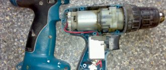
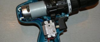
Let's analyze the disassembly, using a Makita screwdriver as an example:
- We remove the block housing where the battery is located.
- We remove the screws that connect the two halves of the case using a Phillips screwdriver.
- We take out everything contained inside the tool body.
- Disconnect the reverse button.
- We remove the speed switch.
- Disconnect the engine and gearbox.
Disassembly is complete.
Disassembly
Screwdrivers are disassembled following a certain sequence:
- The battery is removed (if it is provided for in the design of the product).
- The screws connecting the two parts of the housing are unscrewed.
- The top part is removed.
- Contents are being retrieved.
- The button is disconnected.
- The speed switch is being removed.
- The motor, gearbox, adjusting coupling and cartridge are disconnected.
Disassembly and repair of coupling Interskol DA-12ER-01
: Group: Life channel:.
The abilities of a household screwdriver.
Often the box is a fairly powerful metal element, but plastic models are cheaper. The motor shaft of the device is tilted by a gear; the gearbox has three gears. This drive is called planetary. The box itself is quite easy to remove from the case and easy to assemble.
READ Which Screwdriver To Choose For Your Home
To prevent the gears from falling out of the box, they are inserted at an angle. This prevents the gears from falling out when tilted. Gearbox
is removed from the ratchet along with the housing. The cartridge is fixed by a screw; There is a cartridge thread for unscrewing it, which is correct.
How to disassemble a screwdriver
The screwdriver is disassembled in the following sequence:
- Remove the battery.
- Unscrew the screws connecting the two halves of the case.
The screwdriver body consists of two parts, connected by a fairly large number of screws. to disassemble it, you need to find all the attachment points
- Remove the top.
- Remove the contents.
- Disable the button.
- Remove the speed switch.
- Disconnect the engine, gearbox, adjusting sleeve and cartridge.
The screwdriver button is an integral part of the switching mechanism, which is connected to the engine, so when disconnecting the button from the socket on the body, care must be taken not to break the wires.
To disconnect the screwdriver gearbox from the motor, you need to unscrew the four screws located at the contact point of the two plastic covers.
Electrical faults.
Symptoms of electrical problems include the following: • the tool will not turn on; • the rotation of the working tool in reverse mode does not change; • speed is not regulated. The procedure for checking the reasons if the tool does not turn on: 1. It is necessary to check the battery. If the battery level indicator shows very little charge, try charging the battery. Charging does not help - this is a sign of battery failure. In this case, open the device with batteries. Each element is tested for voltage, which should be in the range of 0.9-1.2 V. Replace elements if necessary. If the battery is working, then the screwdriver will have to be disassembled to find out the reason. To do this, unscrew the screws around the perimeter of the case using a screwdriver. There are usually about 8-9 screws.
2. If the screwdriver still does not work, check the transformer windings with a tester. 3. After disassembling the case, check the start button and lead wires. To check the electrical circuit you need a multimeter. The device will indicate the location of the fault. Don't rush to disassemble the start button. If disassembled carelessly, some small parts may jump out of the button body and scatter around the room. 4. Check the condition of the fuse, which is located near the transformer. If the button and all motor circuits are in good condition, the brushes or motor windings may be faulty.
Operating principle of the gearbox
Sketch 1. Typical design of a screwdriver box.
Hammer. A comfortable and common device during operation, the beginning of its introduction is associated with flights into outer space, where astronauts used it. New models of screwdrivers are being produced, so the demand for them does not fall. This device is applicable for various household items, also repairs.
Act screwdriver gearbox
recalls the process of operation of a drill gearbox; a distinctive feature in all this is the configuration of the part and the gear ratio. The gearbox of any of these tools requires constant inspection. The uninterrupted operation of these devices is associated with repeated checking of the working condition of the gears and lubrication of the gearboxes, which What is a gearbox?
READ How to Remove an Anchor from a Hammer Drill
Charger repair
Frequent charger failures:
- The fuse is blazing;
- The network cable breaks;
- The primary winding of the transformer is cut off;
- Diodes break through.
If we disassemble the screwdriver charger, we will see a step-down transformer and a board. The voltage is supplied via the power cable to the primary winding of the transformer. The fuse is switched on alternately with the mains winding, so it overheats first and protects the winding from damage. From the secondary winding, voltage is supplied to the diode bridge. If charging passes current, then yellowness appears around the diodes. The transformer windings overheat and the diodes break down.
The charger for a screwdriver consists of a step-down transformer and a board with electronics.
- Measure the primary resistance with a multimeter. If it is not there, it means the circuit is broken and no voltage is supplied to the primary winding. The fuse is located under the transformer insulation near the wires connected to the network. Check with a tester.
- If the fuse is good, check the power cord to see if it is broken.
- If the wire is ok, check the windings. Replace the transformer if it breaks.
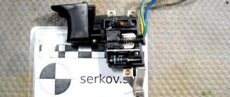
How to fix the Interskol screwdriver button
If charging from the battery is normal, but the tool does not turn on, you need to check the condition of the screwdriver power button.
To do this, after disassembling the device’s body, we gain access to its button. At the terminals that come from the button, you need to measure the voltage level using a multimeter. In this case, the battery must be in an active state. If voltage is supplied, the button contacts must be short-circuited using clamps. In this case, the multimeter switches to Ohm mode. If the voltage is close to zero, this means that the button is in working condition. Otherwise, the button needs to be repaired.
Unsolder the old switch
First you need to disconnect the old switch from the screwdriver body. A soldering iron is used for this. We must not forget about the need to fix the polarities on the sealed contacts of the old button.
Solder a new switch
If you had to buy a new button, you need to pay attention to the fact that it must be completely identical to the old one, have the same dimensions and fit tightly into all the grooves of the tool body. If there are small errors, you can correct them with a file and sandpaper.
Observing the polarities, solder the new button to the contacts of the electric motor. To make sure that all operations were performed correctly, experts recommend checking the button for turning on and the smooth rotation of the screwdriver. Only after this can you begin assembling the case.
How to save on repairing buttons for a BOSCH screwdriver
Fundamentally ! When disassembling the gearbox, what remains to be done is for our client to check the steps with the assembly diagram presented in the product passport.
- They snap out the iron plate and dump out the contents of the first stage of the gearbox.
- After unscrewing the connecting bolts, it is disassembled into two halves.
- Remove the 2nd stage gears from the housing.
- They inspect the parts, identify deficiencies and either eliminate them or replace the unit.
- After eliminating the defects, the screwdriver is assembled in reverse order.
Let's look at the repair of the Interskol Da-18ER screwdriver due to a charger failure. The failure is manifested in the fact that when turned on, no indicator lights up, and the device itself heats up. Where to begin? And you need to start, as usual, with disassembly and measurements:
- To determine the prerequisites, it is necessary to unscrew the screws connecting the halves of the charger housing. It consists of a transformer and an electrical board. Today, a temperature sensor is included in the transformer circuit, which burns out and turns off the device when the coils heat above 130◦ C.
- First you need to measure the resistance on the primary winding of the transformer. If the indicator is equal to zero, then there is a break in the network.
- Then you need to move on to checking the fuse. It is located under the transformer insulation.
- If the integrity of the fuse is not broken, the network cable is checked for breaks.
- For which the design is intended to prevent damage to the supply wire, you need to ring the windings of the transformer. If a breakdown is detected, the transformer must be replaced.
- The resistance on the secondary winding must be made minimal, this indicates its integrity and performance.
- Then you need to check the diode bridge - alternately apply the dark probe of the tester to the minus, and the reddish one to the plus of each diode. If the measurement value is equal to zero, then the diode must be replaced if the passage of the diode exceeding the zero mark is considered working.
How to disassemble the cartridge + (Video)
If the cartridge fixation is conical, then it is simply removed - by carefully hitting the block body with a hammer. If the fastener is threaded, the following steps will be needed:
- Unscrew the screw with the left-hand thread in a clockwise direction.
- We squeeze the hexagon in a vice, place the key on it and hit it with a hammer. Likewise, the cartridge should move from its original position. You can choose one more option:
- Place the screwdriver on a flat surface, on a table, for example.
- Turn it on.
- Observe whether the cartridge has moved from the table. when struck by a hexagon.
It also happens that all of the above methods do not work, and then there is only one thing left to do - disassemble the screwdriver, after which:
- Remove the gearbox and spindle;
- Place the assembly in the clamps of a vice;
- Take a pipe wrench and then disconnect the chuck.
And if there is debris in the gearbox, then that’s what you need to do.
https://youtu.be/Y_BuGSHAEeM
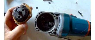
How to replace brushes
Each of the graphite brushes is located at the end of the motor near its connection with the button. Graphite brushes are located at the end of the motor on the side connected to the button. The brush can be located in the middle of the engine housing under the rear covers or outside. If the wear of one brush is at least 40%, then two are needed. You also need to check your contacts. If the brushes have wear, this is indicated by:
- the engine runs jerkily;
- the occurrence of sounds unusual for working equipment;
- the appearance of sparking and a burning smell.