This went on for a long time until, in 1907, Canadian inventor Peter Robertson patented the Robertson screw with a standard square hole into which the tip of a screwdriver was inserted. Since that time, screws began to be produced on an industrial scale and used in households. Later, in 1934, inventor Henry Phillips modified the screw head and a screw with a Phillips notch appeared, into which a corresponding screwdriver was inserted. By that time, the engine had already been invented and the idea of creating a “rotator of screws and screws” was in the air. However, there were big problems with the batteries - their weight and dimensions. The problem was solved only in the 1980s, when the first nickel-cadmium Ni-Cd and lithium-ion Li-Ion batteries appeared.
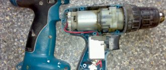
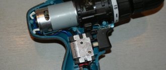
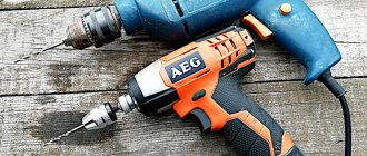
The USA and Japan were the first to master the production of household and professional products. All this happened thanks to the advent of new energy-intensive electricity batteries. We will urgently change them inside the Interskol DA-10/10.8 ER cordless drill-driver that fell into my hands. The malfunction was this: when the button was pressed, the engine simply did not spin, but the LED lighted up , although the light was weak.
Disassembling the screwdriver battery
Let's start repairing the screwdriver battery. We remove the battery from the screwdriver handle and unscrew the three screws that are located under the sticker at the bottom.
After unscrewing the screws, carefully move the hooks of the latches, as in the photo. And remove the bottom part of the plastic battery case.
Inside we see lithium-ion banks from the Chinese company HighStar, model ISR18650-1300 Li-Ion. This means that the batteries have never been changed. Because it is known that Interskol purchases batteries from this company and inserts them into almost all of its products.
The photo below shows the insides of the screwdriver battery in all its glory with three cans, which were produced back in 2011. These lasted five years with active use at a construction site. So the result is very worthy. They usually die earlier, probably they were not used in cold weather.
To replace the battery banks you need to disassemble it further. I advise you to remember the location of the plus, minus and charging contacts so as not to confuse the wires during reassembly.
Pay attention to the voltage control board on the batteries - especially often they fail. It is imperative to ring suspicious radio elements on this board.
We check the voltage at the battery output - it turned out to be 4.4 volts, but it should be 3.7 x 3 = 11.1 volts normally and 10.8 volts with minimal charging. In general, the banks are dead - they definitely need to be changed.
Design of a charger from a screwdriver
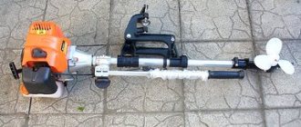
Without a doubt, power tools greatly facilitate our work and also reduce the time of routine operations. All kinds of self-powered screwdrivers are now in use.
Let's look at the device, circuit diagram and repair of a battery charger from a screwdriver.
First, let's take a look at the circuit diagram. It is copied from a real charger circuit board.
Charger circuit board (CDQ-F06K1).
The power part of the charger consists of a GS-1415 power transformer. Its power is about 25-26 watts. I calculated using the simplified formula that I already discussed here.
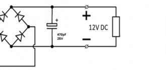
A reduced alternating voltage of 18V from the secondary winding of the transformer is supplied to the diode bridge through fuse FU1. The diode bridge consists of 4 diodes VD1-VD4 type 1N5408. Each of the 1N5408 diodes can withstand a forward current of 3 amperes. Electrolytic capacitor C1 smoothes out voltage ripples after the diode bridge.
The basis of the control circuit is the HCF4060BE , which is a 14-bit counter with elements for the master oscillator. It controls the bipolar transistor of the pnp structure S9012. The transistor is loaded onto the electromagnetic relay S3-12A. The U1 chip implements a kind of timer that turns on the relay for a given charging time - about 60 minutes.
When the charger is plugged in and the battery is connected, the JDQK1 relay contacts are open.
The HCF4060BE chip is powered by a zener diode VD6 – 1N4742A (12V). The zener diode limits the voltage from the mains rectifier to 12 volts, since its output is about 24 volts.
If you look at the diagram, it is not difficult to notice that before pressing the “Start” button, the U1 HCF4060BE chip is de-energized - disconnected from the power source. When the "Start" button is pressed, the supply voltage from the rectifier is supplied to the 1N4742A zener diode through resistor R6.
Next, the reduced and stabilized voltage is supplied to pin 16 of the U1 microcircuit. S9012 , which it controls, also opens
The supply voltage through the open transistor S9012 is supplied to the winding of the electromagnetic relay JDQK1. The relay contacts close and power supply is supplied to the battery. The battery begins to charge. The VD8 diode ( 1N4007 ) bypasses the relay and protects the S9012 transistor from a reverse voltage surge that is formed when the relay winding is de-energized.
The VD5 diode (1N5408) protects the battery from discharge if the mains power is suddenly turned off.
What happens after the contacts of the “Start” button open? The diagram shows that when the contacts of the electromagnetic relay are closed, the positive voltage through the diode VD7 ( 1N4007 ) is supplied to the zener diode VD6 through the quenching resistor R6. As a result, the U1 chip remains connected to the power source even after the button contacts are open.
Replaceable battery.
The GB1 replacement battery is a unit in which 12 nickel-cadmium (Ni-Cd) cells, each 1.2 volts, are connected in series.
In the schematic diagram, the elements of a replaceable battery are outlined with a dotted line.
The total voltage of such a composite battery is 14.4 volts.
There is also a temperature sensor built into the battery pack. In the diagram it is designated as SA1. Its operating principle is similar to the KSD series thermal switches. Marking of thermal switch JJD-45 2A . Structurally, it is fixed to one of the Ni-Cd elements and fits tightly to it.
One of the terminals of the temperature sensor is connected to the negative terminal of the battery. The second pin is connected to a separate, third connector.
The operating algorithm of the circuit is quite simple.
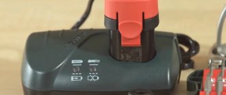
When plugged into a 220V network, the charger does not show its operation in any way. The indicators (green and red LEDs) do not light up. When a replacement battery is connected, the green LED lights up, indicating that the charger is ready for use.
We continue to disassemble the Interskol screwdriver battery
This can be done in several ways - you can unsolder the wires that go to the board.
You can also simply remove the contacts from the top battery cover. The photo shows what shape the curved contacts have, so you can easily remove them yourself.
Under the plastic cover we see how the batteries are connected to each other. They were spot welded . This solution is used in almost any battery of another tool. This is a reliable and gentle battery connection. At the same time, the destructive heating of the lithium batteries themselves is minimal.
Carefully tear off or bite off the metal tape with pliers to disconnect the cans from each other. On the board side, they were also connected to each other with tape and placed on a cardboard spacer with glue. This is done so as not to short anything on the board. You must remember to return it to its place when reassembling the battery.
Due to the lack of a spot welding machine, we will solder new lithium-ion batteries with a well-heated, powerful soldering iron very quickly. We remember that heating reduces their service life and is generally explosive.
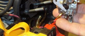
Pay special attention to the condition of the wires inside the battery. They may be broken or frayed. They need to be properly insulated or replaced with fresh ones. Since I was repairing a screwdriver battery on the go in the field, I had to use a brilliant invention of an engineering mind. I took out blue electrical tape.
When disassembling the battery of the Interskol DA-10/10.8 ER screwdriver, I was pleasantly surprised - they installed a thermal sensor to monitor the temperature of the batteries. It turns out that if it overheats, the protection circuit turns off the power until the temperature is restored to normal. True, the owner has never been able to drive him into this mode. We carefully tear off this thermal sensor so as not to break it - then we will place it in the same place on the new cans.
Solder the batteries
It can be done in different ways, for example with thick wires. I decided to solder some torn metal strip taken from old cans. First, I tinned the tapes in the places of future contacts on both sides. Then, using a well-heated soldering iron with a drop of solder, I tinned the battery contacts. But so that they do not heat up too much - let them cool. Then I pressed the tape to the contacts of the cans and soldered the tape, again without severe overheating.
The most difficult thing to solder is the negative terminals, but it goes very quickly. True, it is better to wash the flux later to clean the insides of the battery.
Now the most important thing. What batteries were used when repairing the battery of the Interskol DA-10/10.8 ER screwdriver, you ask? Well, I won’t hide it. These were the most Chinese of the cheap cans that the owner of the device honestly bought in the store. from Bailong with a fictitious capacity of 8800 mAh. This is of course a laugh and God forbid they have 2200 mAh. Judging by how long the screwdriver worked after the repair on a full charge. I would reduce this figure by half. But nevertheless, the screwdriver was urgently repaired and it makes the owner happy.
When assembling, do not forget to return the cardboard spacer between the cans and the board. This is so that fresh soldering does not short-circuit anything on the board.
This completes the repair and restoration of the lithium-ion battery of the Interskol DA-10/10.8 ER screwdriver. Almost all batteries from popular screwdriver manufacturers are repaired in approximately the same way :. This concludes my story about repairing a screwdriver battery. Ask questions in the comments. Better yet, in the corresponding thread on our forum or write to the Soldering Master personally by email.
Sincerely, Master Pike. Happy renovations!
Scheme, device, repair
Without a doubt, power tools greatly facilitate our work and also reduce the time of routine operations. All kinds of self-powered screwdrivers are now in use.
Let's look at the device, circuit diagram and repair of a battery charger from a screwdriver.
First, let's take a look at the circuit diagram. It is copied from a real charger circuit board.
Charger circuit board (CDQ-F06K1).
The power part of the charger consists of a GS-1415 power transformer. Its power is about 25-26 watts. I calculated using the simplified formula that I already discussed here.