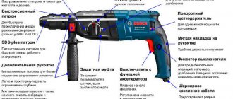
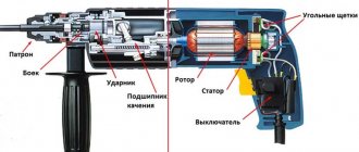
Features of the Hitachi hammer drill
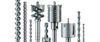
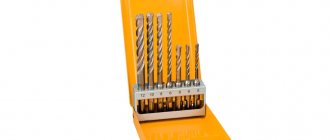
The three-mode hammer drill Hitschi DH24PC3 is produced by Japanese manufacturers. The power of this hammer drill is 800 W. The rotary hammer has a smooth speed control of 0...1150 rpm with an adjustable blow frequency of 0...4600 rpm. The impact force is 3.2 J. The weight of the hammer is 2.4 kg. The Hitachi DH24PC3 hammer drill is equipped with an SDS-plus keyless chuck. Hitachi rotary hammers are designed for drilling holes up to 24 mm in diameter in concrete in drilling and impact mode. In the chiselling mode, the hammer drill helps to remove tiles and make recesses for laying cable and tubular communications. In drilling mode, the hammer drill allows you to drill holes up to 32 mm in wood and screw in screws using additional attachments. The hammer drill allows for reinstallation of the front handle at any angle, which creates additional convenience in hard-to-reach places.
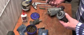
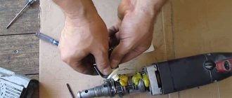
Disassembly procedure for a Hitachi rotary hammer
To repair a Hitachi DH24PC3 rotary hammer, you need to perform a technological operation such as disassembling the tool. When starting disassembly, prepare the workplace, select tools, related materials, and documentation. A flat surface covered with clean paper or material is suitable as a workplace. The place should be evenly and sufficiently illuminated. For tools, prepare pliers, screwdrivers, pliers, a screwdriver, and a vice. For documentation, you will need a disassembly diagram, a lubrication diagram and the attached instructions.
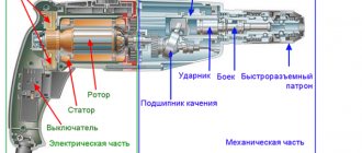
Hitachi DH24PC3 hammer drill diagram
Disassembling the Hitachi DH24PC3 rotary hammer begins with dismantling the keyless chuck.
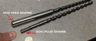
Disassembling the SDS-plus type keyless chuck
To disassemble the hammer drill, you need to remove the keyless chuck:
- • Using a screwdriver, remove the protective rubber boot pos. 1;
- • Pull the locking ring pos.2;
- • Carefully remove the casing pos. 3;
- • Press on the steel ring pos. 4 and the guide washer pos. 5, remove the fixing ball pos. 21;
- • Remove the steel ring, guide washer, conical spring pos.6;
- • All that remains is to get the washer pos. 7 and the retaining ring pos. 8.
The keyless chuck is disassembled.
SDS-plus keyless chuck diagram
Disassembling the three-position mode switch
Proceed to dismantling the mode switch pos. 20A. Pre-set the mode switch to the “Shock” position. By pressing the button pos. 17, turn the switch counterclockwise to an angle of 15º and remove it from the engagement.
Video of disassembling the Hitachi DH24PC3 rotary hammer
Video:
At the next stage of disassembly, the inscription plate on the body of the Hitachi DH24PC3 hammer drill must be removed. It is located on the left side of the body when viewed from the handle. It is removed using a screwdriver using the prying method.
Removing the nameplate
Disassembling the case
Proceed to disassembling the case. Place the body of the hammer drill vertically, resting it on the handle. Using a screwdriver or screwdriver, unscrew the 4 screws, item 9. To remove the cover of the mechanical unit, you need to press the lever in the hole of the removed mode switch and pull the cover up. An aluminum intermediate housing is installed in the cover of the mechanical block, in which the barrel of the impact mechanism is pressed. The body of the mechanical unit consists of two parts: an internal aluminum and an external plastic one.
Separating the barrel block cover from the stator housing
Disassembling the mechanical unit
To disassemble the mechanical unit, several separate operations must be performed. At the first stage, the intermediate shaft is dismantled, then the barrel of the impact mechanism is removed and its individual components are dismantled.
Disassembling the intermediate shaft
The intermediate shaft pos. 47 is inserted into the inner housing pos. 39. To dismantle it, simply pull the shaft out of the inner housing.
Intermediate shaft with mode switch
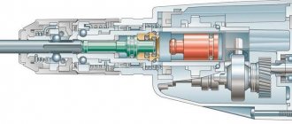
Several parts are assembled on the intermediate shaft, the most important of which are the bearing and the mode switch. The operating principle of the hammer drill is simple. The torque is transmitted from the helical gear of the gearbox (not shown) to the helical gear pos. 1, mounted on the intermediate shaft.
Rotary and reciprocating torque transmission unit
Then the torque is transmitted through the small spur gear of the intermediate shaft to the large spur gear mounted on the shaft of the impact mechanism barrel. At the same time, with the help of the drunken bearing pos. 2, the reciprocating impulse is transmitted to the piston of the impact mechanism. The mode switch pos. 4, using the clutch pos. 3, turns on or off the transmission of the shock impulse or rotational movement. To disassemble the intermediate shaft, it is necessary to sequentially remove the helical gear, the rolling bearing with the clutch, and the mode switch.
Removing the impact mechanism barrel
The barrel shaft of the impact mechanism is pressed into the plastic cover of the mechanical block. To get the barrel shaft, pos. 24, you need to remove the retaining ring, pos. 8, from the outside of the mechanical block cover. When the retaining ring is removed, you can begin to press out the barrel of the impact mechanism using a press or device. It is not advisable to remove the barrel by impact, so as not to damage the plastic body of the hammer drill. If you don’t have a press, then a large bench vise will do. But you need to make a simple device for them from a solid material, for example, wood.
Device for pressing out the barrel of a Hitachi DH24PC3 hammer drill
The new barrel for the Hitachi DH24PC3 rotary hammer is sold assembled. Although you can buy just a barrel, but one made in China.
New barrel assembly
Disassembling parts of the impact mechanism
To create a shock impulse, the piston sleeve of the hammer drill, pos. 39, is inserted into the barrel of the impact mechanism, into which, in turn, the firing pin, pos. 29, and the hammer of the impact mechanism, pos. 37, are inserted. A piston pin is fixed in the tail part of the piston liner, into the hole of which a rolling bearing connecting rod, pos. 53, popularly called a “drunk bearing,” is inserted.
Hitachi hammer drill barrel diagram
Remember! During repairs, all rubber components must be replaced.
What types of bearings are used in the Hitachi DH24PC3 rotary hammer and their Russian analogues
The Hitachi DH24PC3 rotary hammer uses the following Japanese-made bearings:
- • Pos. 15 bearing 37 mm, article number 6904DD, dimensions 20x37x9, Russian equivalent 1000904;
- • Pos.56 bearing 19 mm, article 626VVM, dimensions 6x19x6, Russian equivalent 26;
- • Pos. 60 bearing 22 mm, article 608DDM, dimensions 8x22x7, Russian equivalent 80018;
- • Pos.66 bearing 22 mm, article 608VVM, dimensions 8x22x7, Russian equivalent 60018;
Now you can proceed to disassembling the electrical part of the Hitachi DH24PC3 rotary hammer.
Assembling the electrical part of the Hitachi DH24PC3 rotary hammer
Let's divide the assembly of the electrical part of the hammer drill into stages.
Stator assembly
The repaired or new stator, pos. 65, is installed in the stator housing, pos. 68, and secured using M4×50 fixing screws, pos. 64. Stator article number 340635F.
Stator and rotor assembly diagram
The stator is closed from above by the guide of the electric motor impeller, pos. 63. The stator wires are routed to the control button pos. 70B.
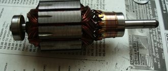
Rotor assembly
The hammer drill uses a 220-230V electric motor armature, article number 360720E.
A new or self-repaired rotor, pos. 62, is installed in a socket in the inner housing, pos. 41, with a felt gasket, pos. 57, an o-ring, pos. 58, a sealing gasket, pos. 59, a bearing 608DDM, pos. 60, and pre-installed on the rotor shaft. steel gasket pos. 61. Bearing dimensions 8x22x7, Russian equivalent 80018.
The assembled rotor is inserted with a helical gear into the mechanical block of the hammer drill.
All that remains is to connect the mechanical block and the stator housing.
When you insert the rotor into the stator housing, first remove the carbon brushes along with the brush holders.
Disassembling the electrical part of a Hitachi rotary hammer
Disassembling the electrical part of the hammer drill begins with dismantling the carbon brushes. To get out the electric carbon brushes, you need to open the hammer drill handle by unscrewing the cover screws using a screwdriver or screwdriver.
Removing carbon brushes
Pry the latches with a screwdriver and release the carbon brushes pos. 69, 72 using pliers.
How to disconnect the rotor from the mechanical unit
Taking the mechanical part in your right hand and the stator housing in your left, pull them in different directions, shaking them. The rotor pos. 62 will come out of the stator housing. Now take the rotor itself in your left hand and carefully pull it out of engagement with the mechanical part of the hammer drill. The rotor is held in the mechanical part of the hammer drill by friction in helical gears.
Hitachi DH24PC3 rotary hammer
Stator disassembly
To remove the stator pos. 65, you need to remove the plastic protection pos. 63 and unscrew the screws pos. 64 holding the stator in the housing. Don't forget to disconnect the stator wires from the switch. To remove the stator from the housing, take the stator housing in your left hand, and a wooden hammer or block in your right hand and tap on the end of the housing. With each tap, the stator will slowly come out of the housing. Read how to check the health of the stator and rotor.
Disassembling control circuits
To remove the switch with the speed controller, you just need to remove it from the body of the handle of the Hitachi DH24PC3 rotary hammer. The hammer drill uses a push-button switch pos. 70V for 220 V, type OLD331454/324536. Carbon brushes pos. 74 are held in special brush holders pos. 75.
Hitachi DH24PC3 rotary hammer control circuit diagram
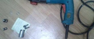
How to disassemble a Japanese Hitachi DH 24PC3 rotary hammer
First, we disassemble the hammer drill by unscrewing several screws in the handle area.
Carefully pry along the seam and remove the handle cover. Underneath, everything is quite sad - dust from construction work during the laying of SCS (structured cable networks, in general, a local network in Russian) ended up inside in all places.
Usually this dust damages the tool. Dust gets clogged and the contacts inside it wear out faster. The same thing happens with electric motor brushes, although they are considered consumables and can be replaced quite easily.
Heavier with bearings, gearbox and impact mechanism - these are expensive components.
The rotary hammer switch has a complex structure - its diagram is often shown directly on the body.
The difficulty is due to the fact that it is necessary to control the large power supplied to the motor, and besides, the current of the windings depends on the degree of pressing on.
Therefore, a complex system of contacts was used inside and a thyristor was installed . In addition, there is a reverse switch on top, which does not make life easier for the repairman.