Tool Maintenance
Let’s summarize briefly and outline the main steps for caring for a hammer drill and maintaining it in good condition.
First of all, lubrication. In some models, you can replenish its reserves without disassembling the case through the holes of the mode switches. In barrel perforators, there is a special cover in the front part for this, but only the crank mechanism and the intermediate gearbox can be lubricated through it.
Lubricating the barrel and firing mechanism almost always requires detailed disassembly and cleaning. The presence of solid particles in this mechanism leads to rapid wear, jamming of the piston, and biting of the stuffing box seals. It is also necessary to lubricate the drill shanks with thick grease and always keep them clean and lubricated; this will significantly extend the life of the chuck.
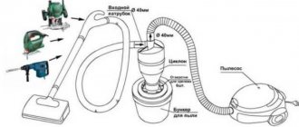
Like any other tool, a hammer drill does not like dust. Therefore, when working on the air intake slot, it is better to pull a nylon stocking or other improvised filter
But even with such precautions, you should periodically disassemble the motor part and thoroughly blow it through, because even the slightest layer of dust on the windings greatly impairs heat dissipation
Malfunctions in the gearbox housing
The body of the HR 2450 model is characterized by high strength; failures in this unit are quite rare. But it happens that certain troubles occur here too. If the housing was received along with the needle bearing, it means that its seat is badly worn. When this part becomes extremely loose, the housing should be replaced.
READ How to Remove the Bobbin from the Trimmer
Sometimes the seat of the intermediate shaft is broken. The repair is expected to be similar to the first case.
The gear housing shaft has an oil scraper ring. If it is damaged by construction dust (this happens extremely rarely) or careless actions of a repairman, it is replaced along with the housing.
The same procedure is performed in case of failure of the mode switch holes. The listed types of breakdowns are typical for counterfeit copies.
Operating rules or how to protect the device from damage?
Prevention is an effective method that will allow you to avoid many breakdowns in the operation of the device. In this case, it implies proper use. You should start with how to insert drills correctly: firmly grasp the chuck and pull the spindle axes. When the hole widens, you can install the drill by lowering the chuck. If you are going to work in impact mode, be sure to lubricate the shanks with a lubricant, choosing it according to the manufacturer, but there is also a universal solution from the Litol company, which has also earned a lot of positive feedback from users.
To protect yourself and preserve the cordless hammer drill when drilling concrete, use a safety coupling. And all due to the fact that there may be reinforcement in concrete structures - the drill will simply get stuck in it. If there is no clutch, use low speeds, and do not hold the handle very tightly - if the tool suddenly gets stuck in the fittings, you must quickly release it from your hands, otherwise bruises and contusions cannot be avoided.
How to remove a bearing from a power tool armature: some practical tips
Today, many home craftsmen and professional craftsmen have a whole arsenal of power tools that help them cope with household and repair and construction tasks.
Hammers, jigsaws, grinders, drills - all of them significantly simplify and speed up work. However, it happens that a power tool breaks down. Don't rush and throw it in the trash because of this. Due to intensive use, parts wear out, and therefore the equipment cannot operate in normal mode. If you know how to remove the bearing from the armature of a power tool, you can extend the life of your “assistant”. Timely replacement and lubrication of parts allows you to operate the device for a longer time. The main task of a power tool motor is rotation. The armature is the important part of the device that causes the working mechanism to rotate. The service life of the part depends on the power and rotation speed, as well as the activity of using the equipment. To reduce friction during the movement of parts, bearings are needed. They ensure smooth rotation and improve the running of the working mechanism of the power tool. If you take care of the bearings and lubricate them in a timely manner, their service life increases several times.
Breakdown of the gearbox and barrel
Problems associated with chuck rotation and interruptions in the operation of the impact mechanism are usually located in the gearbox part of the hammer drill. Depending on the location of the engine, the design and operating principle of this unit may vary. What is common to both types of structures is the presence of a raster bushing (barrel) in which the pneumatic impact mechanism is located. To access maintenance, you need to remove the top rotation mode switch and unscrew the front gear part of the tool from the motor part; usually it is secured with four powerful screws. Sometimes it is necessary to first remove the plastic covers. After this, the raster bushing is knocked out of the metal gearbox housing with a rubber hammer.
In rotary hammers with a horizontal rotor position, rotation is transmitted due to a toothed gear fixed around the circumference of the barrel and receiving force through a ratchet mechanism pressed by a spring (safety clutch). Here, the difference in the design for different types of rotary hammers lies in the shape of the drive gear: for horizontal ones it is longitudinally helical and mounted on the armature shaft, for vertical ones it is conical, serving as the output of the transfer and reduction gearbox installed above the engine. The driven gear differs only in the direction of the teeth.
The most obvious differences are the impact mechanism. The transfer of rotational motion into translational motion in barrel hammer drills occurs due to a crank mechanism driven by an intermediate gearbox. With “horizontals” everything is somewhat simpler; here there is a pumping (drunk) bearing with an additional shaft mounted on two rolling bearings. The piston part has a not too complicated structure: a piston-striker moves inside the outer sleeve of the sleeve, and in the front part there is a so-called industrial mass - a striker catcher. Sometimes the last two elements have a telescopic device on a ball-slot fit, which works in a similar way to an SDS cartridge. Almost always, to disassemble the barrel, you need to remove the locking ring, tightly seated inside the outer barrel cup, by prying it through the side hole.
Maintenance of the gear-piston part includes complete disassembly, washing of dirt and metal shavings in kerosene, and replacement of lubricant. Barrel hammer drills are equipped with a crank drive cover to add additional lubrication. Both types of mechanisms are very sensitive to clogging and wear of the rolling elements. The situation can be aggravated by aging of the piston mechanism's o-rings, which allows dust particles from the cartridge to penetrate into the bushing.
Please note that the gear part contains many small parts and the revision must be carried out, adhering to the assembly diagram, which is indicated in the passport documentation of the tool
We disassemble the gearbox
To get to the mechanical part, you will need to remove the plastic housing.
The procedure for disassembling the mechanical part of a Makita rotary hammer: First, remove the black protective plastic case. The case is removed after you unscrew the four screws securing the case from the end. By pressing on the end of the shaft you will press the gearbox out of the housing.
After removing the housing, you need to separate the rotor from the gearbox. The gearbox is the general mechanical part. The rotor is separated from the mechanical part (gearbox) simply. You need to clamp the gearbox with your right hand, and clamp the rotor with your left hand. While rocking, pull both parts in opposite directions. The rotor is held in the gearbox by friction of helical gears. The main malfunctions of the Makita rotary hammer occur in the mechanical part of the tool.
The most typical malfunction for the mechanical part is the failure of the impact mechanism.
Disassembling the impact mechanism The impact mechanism is assembled on the inner housing and consists of a gearbox shaft and an intermediate shaft. The rotational motion is transmitted through helical gears to the intermediate shaft.
The gearbox shaft is a hollow shaft in which the cylinder moves freely.
A small spur gear mounted on the intermediate shaft transmits rotation to the large spur gear of the gearbox shaft, in which the impact mechanism is mounted. And translational movements are simultaneously transmitted to the gearbox shaft of the impact mechanism due to transmission from the rolling bearing of the intermediate shaft to the cylinder moving in the gearbox barrel.
Let's move on to disassembling the intermediate shaft.
Disassembling the intermediate shaft
Mounted on the shaft pos.40 is a helical gear pos.42, to which rotation is transmitted from the rotor gear, a rolling bearing 608zz pos.41, which transmits translational motion to the hinge pos.34 of the piston pos.32. On the other side of the shaft, a clutch coupling is installed, pos. 39, spur gear 10, pos. 80, compression spring, pos. 38, retaining ring S-7, pos. 37, bearing 606zz, pos. 36. Particular attention should be paid to the condition of the rolling bearings. The hammer drill has imported bearings. Installation of domestic bearings is allowed. Bearing 606zz can be replaced with 80016, bearing 609zz can be replaced with 80019.
Let's move on to disassembling the impact mechanic shaft
Disassembling the impact mechanism shaft Disassembling the barrel of the Makita 2470 hammer drill is a simple process if you use the Makita hammer drill design diagram. The shaft is a barrel, pos. 21, in which the impact mechanism is assembled. A gear, pos. 19, is attached to the barrel, which is pressed by a spring, pos. 18, through a washer, pos. 17, and secured with a retaining ring, pos. 16. The cylinder, pos. 32, moves in the barrel, acting on the firing pin, pos. 24. On the reverse side of the striker there is a metal ring, position 27, which transmits the blow to the drill. When is it necessary to replace the hammer drill barrel?
Most often the metal ring fails. Striker Cylinder with striker
We've sorted out the disassembly. We replace the parts with serviceable ones and get ready to assemble. Learn more about lubrication and assembly of the hammer drill.
Assembly procedure for quick release chuck
Assembly is carried out on a clean surface. The parts are pre-washed, dried and lubricated with a thin layer of recommended lubricant.
The gearbox shaft is lubricated with Makita 183477-5 SDS-PLUS grease. All incoming parts of the cartridge are assembled onto the shaft in a certain sequence. Having installed the conical spring pos. 6, put on the guide washer pos. 5 and fix it with the ball pos. 20, inserting it into the groove of the gearbox shaft. All that remains is to put on the ring pos. 4, the coupling casing pos. 3, secure the parts with the locking ring pos.2. At the last stage, insert the protective tip pos. 1 into the end of the chuck. The repair of the Makita 2450 hammer drill chuck is now complete. It remains to check its quality by inserting a drill into the cartridge. When assembled correctly, the cartridge keeps the drill from spontaneously falling out. The cartridge is assembled.
Work process
Disassembling the hammer drill should begin by removing the protective rubber cap - boot. It can be easily removed, just grab it with your fingers and pull it off the barrel.
Then, press on the plastic cover and compress the SDS mechanism retaining spring. remove the retaining ring with a screwdriver.
Using a screwdriver, remove the stopper
The cover is removed from the barrel, and behind it, compressing the spring again, we pull out the retaining ball along with the spring and the figured washer.
Disassembling the SDS mechanism
After which the operating mode switch is disassembled. Under the cover that holds the red locking button, there is a special slot for a screwdriver. By inserting a screwdriver into this groove and prying the cover slightly, first from one edge and then from the other, carefully remove it. You should not apply significant effort here; the lid is still plastic and may break. The red button along with the spring is removed from the switch body, and it is moved to the left all the way, just beyond the drilling mode. It is from this position that it is removed from the gearbox. For this operation, the switch must be lightly picked up with thin screwdrivers on both sides and removed along with the rubber o-ring.
Removing the rotary hammer mode switch
Now the gear box is removed. Using a Phillips screwdriver, unscrew the four bolts connecting the box to the stator housing. Then, holding it with your hand, you need to lightly hit the end of the barrel with a mallet so that the box comes off the gearbox.
READ How to Disassemble a Makita Hr2450 Rotary Hammer
Removing the gearbox
After removing the box, remove the barrel from the gearbox. It comes off easily.
Pull the barrel out of the gearbox
Makita 2450 hums strangely \ About rubber bands / Bearing replacement \ Repair of Makita rotary hammers
Use a rag to remove old grease, wash the barrel with gasoline or kerosene and wipe dry.
So, as mentioned above, it was necessary to completely change the entire barrel. However, this item purchased at the service center turned out to be “as naked as a falcon.” That is, there was absolutely nothing on it and all the parts from the old barrel had to be moved to a new “blank”.
The most difficult operation was removing the firing pin from the barrel body. There are special holes in the barrel body through which the locking ring can be seen. This ring holds the firing pin with rings and rubber dampers in the body seat. Inserting a thin screwdriver into the hole, bend the ring slightly. We do this first on one side and then on the other. The stopper should come out of the groove.
Using two screwdrivers, compress the stopper
Then, from the inside, using a homemade wire hook, we pull the stopper out into the light of day.
Using a wire hook, remove the stopper from the inside.
Next, remove the striker with washers and rubber rings. For assembly, it is necessary to remember or sketch the location of all rings and washers. If something goes wrong, photographs and drawings from the article will help.
Now you need to remove the gear from the shaft. After pressing on the washer and compressing the spring, use a thin screwdriver to remove the retaining ring from the groove. After removing it, remove the washer, spring and gear from the barrel.
Removing the gear wheel
The gear wheel is put on the new barrel and engaged with the splines. Next, a spring with a washer and a stopper are installed on it. You need to insert the locking ring and fix the mechanism in the working position.
To do this, take the barrel in both hands and, resting it in your palms, forcefully compress the spring with your fingers, while simultaneously moving the washer and stopper down. You need to squeeze until the stopper fits into the groove.
Then a firing pin with washers and rubber rings is installed inside the barrel in the order in which it was disassembled. But first you need to pay attention to the condition of the drummer, his appearance.
If the firing pin has gouges and pits after a long period of work or because it was scratched by a broken bushing, then it should be sanded a little. To do this, it is clamped into the drill chuck and processed with fine-grained emery cloth. But if the irregularities are too large, then the striker will be easier to replace.
Assemble the impact mechanism
It is necessary to lubricate the striker with a special lubricant before installation and then use the lubricant during operation. When inserting a drill into a hammer drill , you need to apply a little lubricant to its shank. This extends the service life of the machine.
Having installed the firing pin mechanism into the barrel, we fix it with a locking ring. Using a screwdriver, we try to move the firing pin on both sides inside the barrel. It should move easily in the channel and not jam.
Assembling a new trunk
We install the assembled barrel into the gearbox housing. Putting it on the cylinder with the piston, we engage it with the drive gear and insert it into the body. All parts should be well lubricated during assembly.
Installing the barrel into the gearbox
Then we install the gearbox, having previously lubricated the needle bearing . Using four bolts, we tighten the box to the stator housing and install the operating mode switch in place. To do this, set it in a position slightly to the left of the drilling mode. We insert the red locking button with a spring and move the switch to the drilling mode. We snap the plastic cover and check the operation of the switch.
Reinstalling the mode switch
Snap the cover of the rotary hammer mode switch
Then, as a final touch, the SDS mechanism is assembled. Having installed the mechanism spring, put on the figured washer and insert the ball. Then use a plastic cover to compress the spring of the mechanism and insert the retaining ring. Putting on the rubber boot is no longer difficult.
Compressing the spring with the washer, install the retaining ball
Installing the SDS mechanism
Let's try the hammer drill under load. When the machine is operating, there should be no extraneous noise in the gearbox; the operating mode switch should move easily without jamming. In general, everything should work as before the breakdown.
To install the mode switch into the case, you need to perform some actions: insert the switch into the “drilling” position into the mounting socket until it clicks; move the switch counterclockwise to the “blow” position; turn the switch with a click counterclockwise to the “drilling” position; insert the spring and the red button; Insert the cover on top until it locks into place. The mode switch is assembled.
At the second stage, you should disassemble the quick-release chuck and repair the hammer drill chuck with your own hands. By the way, the cartridge requires disassembly only for Makita 2470 models. The design of the cartridge is quite simple, and anyone with a little knowledge of metalworking skills can handle its repair.
Malfunctions and their causes
Frequent hammer drill malfunctions:
- does not turn on. Check the electrical circuit;
- The hammer drill doesn't hit. Damage to the impact mechanism;
- The tool does not turn or drill. Reasons: armature bearings, armature gear, gearbox;
- the drill flies out and doesn't stay in place. Faulty cartridge or raster bushing;
- sparking in the electrical housing. Reasons: violation of armature winding insulation, wear of brushes, commutator, clogging of brush holders;
- sparking in the area of the power button. Malfunction of button contacts or wires;
- The hammer drill is heating up. The reason is worn brushes, short circuit of winding turns, poor lubrication of the gearbox;
- The hammer drill does not hold the chuck. The retaining ring or retaining washer is broken.
Repair or replacement? The choice is yours!
A handyman with electrical experience can repair the fittings on a drill with his own hands. Start with troubleshooting. In the event of a break or short circuit in the turns of the armature winding, the reason for the “silence” of the punch or the slow rotation of its rotor (accompanied by intense sparking around the perimeter) is easy to establish: a tester. Sparking, as well as an attempt to turn the shock valve in different directions, is the result of short circuiting of part of the turns in the winding. If the spark has the character of a single, but long-lasting spark, the cause is a damaged wire or poor contact with the commutator itself.
When checking, you should also check for the possibility of damage to the valve body. When measuring actual resistance values, the values obtained must be at least several ohms.
During development of a hammer drill, significant imbalance in the axis of rotation of the valve is possible during punch operation. This fault is diagnosed after the open winding is not open. To do this, connect the drill to the rheostat and gradually increase the voltage to the nominal voltage. If during diagnostics the tone of the electric motor changes and the armature oscillations increase, rotor balancing is necessary.
Since it is almost impossible to rewind the anchor at home, it is recommended to use the services of specialized workshops. The price of winding an armature on a rotary hammer for most models (from Bosch, DeWalt, Makita, etc.) depends on the power of the tool and its performance (home or professional). If the drive power does not exceed 1000 W, the service will cost 1000. 1200 rubles, for a drive up to 1500 W. 1500. 1600 rubles, and for more powerful rotating hammers. Up to 2500 rubles. Comprehensive repairs (for example, replacing a bearing) can cost 3500. 4000 rubles. In this case, fault diagnosis in most workshops is free.
Checking with a short-circuited turns indicator (SCI)
There are anchors where the wires connected to the collector are not visible due to being filled with an opaque compound or due to a bandage. Therefore, it is difficult to determine the commutation on the commutator relative to the slots. An indicator of short-circuited turns will help with this.
X in the case
This device is small in size and easy to use.
IKZ device
First check the anchor for breaks. Otherwise, the indicator will not be able to detect a short circuit. To do this, use a tester to measure the resistance between two adjacent lamellas. If the resistance is at least twice the average, then there is a break. If there is no break, proceed to the next step.
The resistance regulator allows you to select the sensitivity of the device. It has two lights: red and green. Adjust the regulator so that the red light starts to light. On the indicator body there are two sensors in the form of white dots located at a distance of 3 centimeters from each other. Attach the indicator with the sensors to the winding. Rotate the anchor slowly. If the red light comes on, it means there is a short circuit.
Proper operation and care of the hammer drill
To ensure that the hammer drill works for a long time, you should follow some recommendations:
- Before fastening the equipment, lubricate the shank with the product specified in the instructions;
- after work, clean the chuck and equipment;
- when working with concrete, remove the drill every 2 cm;
- if you need to drill a large hole, use drills of different diameters so as not to drill with the largest drill at once;
- When doing a large amount of work, take breaks to allow the equipment to cool down. During breaks, you can clean the cartridge;
- Regularly carry out a complete disassembly of the tool for cleaning and lubrication.
If the hammer drill has any malfunction, read the instructions. Inspect the instrument carefully. If you don’t doubt yourself, then do the repairs yourself.
Engine problems
The rotary hammer motor also has a standard design and is not much different from most single-phase commutator electric motors for power tools. The motor stator does not deserve special attention and fails quite rarely. The only thing worth mentioning is that in some models the stator is rigidly fixed in the housing shell and to inspect the engine you will have to disassemble both the tail section with the brush pockets and the front connection to the gearbox.
The drive gear of the gearbox is attached to the rotor shaft on one side, followed by a bearing and a cooling impeller, a magnetic core with windings, a collector current collector and another bearing. The most vulnerable parts of this assembly are the bearings, which are mostly maintenance-free and have a short service life due to operation at high speeds. Their wear is accompanied by the appearance of extraneous noise during operation, vibration and heating of the seats. To replace the bearings, you need to pull them off the ends of the shaft using a puller or a slingshot mandrel, and then install new ones, having previously warmed them with a hairdryer. Don't forget to replace the spacers and o-rings in the correct position.
Another armature element that often fails is the impeller. The entry of large stones through the air intake causes the blades to break off, and sometimes even completely destroy them. In this case, debris and debris get inside the motor, scratch the varnish on the winding wires, and the lack of normal airflow leads to permanent overheating of both parts of the engine. For some motors, it is possible to remove and press on a new impeller, but most armatures have to be replaced as an assembly. This is partly reasonable, because without normal cooling the anchor remains viable for a few minutes.
Damage to the insulation of the windings can cause a short circuit between the turns, which leads to a change in resistance and uneven operation of the motor. The stator resistance can be measured using two lead wires; it should be equal to the nameplate value. Measurements of the armature windings are carried out between two lamellas, and the values may deviate slightly from the passport data, but all windings must have equivalent conductivity.
Short circuits in the windings can be easily identified by the characteristic blackening of the varnish in places of overheating and burning. The black varnish no longer serves as an insulator; such an engine must be replaced immediately. Basically, maintenance of the electric motor comes down to blowing it out of dust, as thoroughly as possible, and cleaning the collector of graphite dust and carbon deposits.
Advice from professionals
Some tips from professionals will help prevent breakage of the angle grinder armature and extend the life of the power tool. Preventing dust and dirt from getting inside the body:
- use a construction vacuum cleaner to remove dust when sawing non-metallic materials;
- pour water over the cut area, reducing dust emissions;
- cover the air intake grilles with gauze or a piece of nylon tights, periodically change/clean this insulation;
- adjust the gearbox so that the direction of rotation of the wheel is turned away from you - dust and other sawing products will be directed away from the air intake grilles;
- Do not place the angle grinder on the ground, in sand, mud or on wet surfaces.
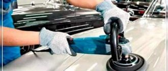
Tips for working with an angle grinder:
- immerse the cutting disc into the material slowly, without pressure;
- help sawing by moving the grinder back and forth;
- compare the volume of sawing and the properties of the material with the technical characteristics and power of the grinder;
- If it is possible to adjust the speed, do not saw at low speeds for too long.
To learn how to check the angle grinder's anchor, see the following video.
Why is it needed?
Rotation in the transmission system is transmitted from the internal combustion engine shaft to the wheels through the gearbox using a clutch disc and basket mounted on the flywheel. The scheme, in principle, is not complicated, but the clutch elements are removed from the gearbox, exposing the input shaft to intense wear.
To reduce imbalance, a kinematic scheme is used:
- a needle bearing is pressed inside the flywheel with little force;
- at the moment of engagement of the disk with the basket, the input shaft changes its spatial position - it extends a few millimeters out of the box towards the crankshaft and the flywheel mounted on it, respectively.
READ How to Sand Wood Floors with a Sander
The designers considered that this translational movement was quite enough for the free end of the gearbox input shaft to fit inside the bearing race without much effort and to receive additional temporary rotation support.
Even under light loads, the bearing cannot have an eternal life, so periodic replacement of the consumable is required. The main problem for the user is how to remove the needle bearing without removing the flywheel itself:
- When dismantling, manufacturers recommend replacing the mounting bolts;
- before removing the flywheel you need to put marks;
- After installing the part back, it is advisable to balance the crankshaft assembly on a dynamic stand.
All these operations sharply increase the engine repair budget; a simple bearing replacement results in partial disassembly of the gearbox, engine and clutch.
Repair: Elimination of insulation breakdown
If the insulation breakdown was small and you found it, you need to clean the area of carbon deposits and check the resistance. If its value is normal, insulate the wires with asbestos. Apply quick-drying “Super Moment” type glue on top. It will seep through the asbestos and insulate the wire well.
If you still haven’t found the location of the insulation breakdown, then try carefully soaking the winding with impregnating electrical insulating varnish. Punched and unpierced insulation will be saturated with this varnish and become stronger. Dry the anchor in a gas oven at about 150 degrees. If this does not help, try rewinding the winding or changing the armature.
Soldering the collector plates
The slats are mounted on a plastic base. They can be erased to the very base. Only the edges remain that the brushes cannot reach.
Worn lamellas
Such a collector can be restored by soldering.
Cut the required number of lamellas to size from a copper pipe or plate. After you have stripped the armature of copper residues, solder it with regular tin and soldering acid. When all the lamellas are soldered, sand and polish. If you don't have a lathe, use a drill or screwdriver. Insert the armature shaft into the chuck. First, sand with a file. Then polish with grit sandpaper. Don't forget to clean the grooves between the slats and measure the resistance. There are lamellas that are not completely damaged. To restore them, more thorough preparation is necessary.
Lightly grind the commutator to clean the plates.
The space under the plate must be expanded with a drill carefully so as not to remove a large layer of insulator.
Find two pieces of copper wire large enough to fit snugly into the groove. Place the cleaned wires in the groove and tin them. Make a lamella blank from copper
It should fit tightly into the groove and be higher than the existing lamellas to make soldering easier.
Tin the workpiece so that there is a lot of solder. It will sit tighter in the groove. Place the workpiece in the groove and attach the soldering iron to it. Hold it until the solder melts.
File off the excess, sand and polish.
If the collector has been completely worn out, then after soldering it will last no more than a month of active use. And plates that are not completely damaged after such repairs can withstand several replacements of brushes and do not become desoldered.
Galvanic extension of collector plates
Reduced copper is very hard. The service life of the collector is like new. Galvanic extension can be used to restore both a completely worn out collector and partially damaged plates.
Completely worn out manifold
The quality of restoration will be the same.
Some plates are damaged
- Thoroughly clean the entire surface of the commutator, including the insulator between the lamellas.
- Wind up bare copper wire with a diameter of about 0.2 millimeters.
- Wrap the armature shaft with tape, and smear the end of the collector with plasticine so that the copper does not grow where it is not needed. And so that the electrolyte does not get on the iron.
- For the bath, cut off the half of a plastic bottle. Wrap electrical tape onto the shaft so that it fits tightly into the neck of the bottle. Insert the anchor into the bottle.
- Take a piece of copper bar. Its size is twice the size of the growing surface. Roll it into a spiral and place it in a bottle.
- Connect the power source with the minus to the surface to be restored, and the plus to the bus bar. One and a half amperes of current per square decimeter of solution. If the commutator is separated from the shaft, wrap it with wire and hang it in a jar on some kind of crossbar so that the electrolyte only touches the worn part of the lamellas. Connect light bulbs of different wattages in series to regulate the current and prevent a short circuit on the vessel. After 24 hours, a restored collector is obtained.
- The collector must be sharpened and the plates separated using a drill or hacksaw blade. Finally, test the collector for any shorts between the plates.
Electrolyte components:
- Copper sulfate - 200 g.
- Sulfuric acid 1.84 - 40 g.
- Alcohol - 5 g. It can be replaced with triple the amount of vodka.
- Boiled water - 800 ml.
Features of pressing on the engine anchor bearing
After you have successfully removed the bearing from the armature, you need to carry out a number of necessary manipulations before assembling the equipment. If you are installing new parts, it is necessary that they match the exact width, inner and outer diameters of the old bearings. It is important that during installation, no dirt or dust gets inside the product, as this can lead to corrosion, chipping and various types of damage. The bearing is mounted on the anchor using a metal pipe, which must first be lubricated. During the pressing process, it is important to ensure that there are no distortions. The following nuances should also be observed:
- Lubricate the bearings with a special thick substance. It can be moisture resistant;
- Only ½ (for equipment with rotation up to 300 rpm) or 1/3 (for higher speed tools) of the bearing chamber is filled with lubricant. You shouldn’t apply more substance, because all the excess will still be squeezed out during rotation.
Sometimes the process of fitting a bearing onto an anchor is simplified if it is preheated in boiling oil. However, you need to be very careful in this case and make sure that the part does not heat above 100 0C.
Today, home and professional craftsmen use several methods to solve this problem. If it becomes necessary to remove the bearing from the armature of an angle grinder or other tool, this can be done using the following devices:
- Pullers. These are special devices that allow you to easily and safely remove bearings of different sizes from the angle grinder’s armature. Using pullers requires virtually no physical force, even if the bearing is tightly seated. Thanks to the centering mechanism, simultaneous installation of the device's grips is ensured. It can be used in any position. Before removing the bearing, you need to clean the armature shaft of the angle grinder from old grease, chips, sand, so that nothing interferes with removing the part. The centering mechanism allows the puller to precisely occupy the seat. If the bearing is intact, and the dismantling process is carried out for inspection, it should be pulled out by the inner ring so as not to damage it. For large armature shafts, grinders use massive pullers with three or four gripping arms, and for small ones, devices with replaceable plates or strips are suitable.
- Hammers, chisels, wrenches and other available tools. In this case, in order to remove the bearing from the armature of the angle grinder, it is heated with gas, compressed in a vice, ground off, chopped and many other operations are performed. These methods, of course, can be effective, but there is a high risk that the part’s seat will be mechanically damaged. And often the bearing itself, after such manipulations without a puller, will be unsuitable for further use. In addition, the performer may be injured due to pieces of the clip getting into the face, eyes or head, which fly apart after impacts.
READ How to properly drill a concrete wall with a hammer drill
As practice shows, pullers are more effective in this situation. They allow you to quickly, easily and without much risk remove the bearing from the armature of a power tool and inspect or replace parts. If you have to periodically carry out such operations, you should acquire such a useful device. The use of improvised devices is only permissible if you have experience in repairing power tools and urgent replacement of the part is required.
How to Remove a Bearing from an Armature If You Don't Have a Puller New Video from the Workshop
How to remove a bearing from an angle grinder rotor
One of the many ways to remove a bearing from a rotor of an electric tool without damaging it
Review of the device from the inside
If the power supply is fine but the grinder is not working, you will need to open the housing to access the motor. As a rule, disassembly is not difficult. But you should follow simple rules that will help you avoid the hassle of reassembly:
It is best to inspect the engine in bright light so that all small parts are clearly visible. The armature should rotate freely around its axis; properly functioning bearings should not make any sound during operation. There should be no traces of melted wiring on the armature, the circuit windings should be intact, without breaks. You can smell the rotor. During the closing of the interruption, the insulating varnish burns and emits a constant specific odor. But such a diagnosis requires some experience.
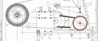
Perforator device
- With the engine installed horizontally.
- With vertical motor.
In all other respects, all parts of the hammer drill are basically similar.
The hammer drill consists of two parts: electrical and mechanical.
Electrical part of the hammer drill
- The main element of the hammer drill is the engine, which consists of an armature and brushes.
- Engine control device.
- Start and stop button.
- Interference suppression elements (capacitor, chokes);
- Power cord.
In some models, the switch is combined with a control device.
Auxiliary mechanisms
Some models may be equipped with additional parts:
- mode switch;
- vacuum cleaner;
- depth limit;
- other.
How to check the functionality of a hammer drill armature?
The sequence of carrying out this kind of routine work is considered using the example of rotary hammers from the Makita brand, although there are no fundamental features for similar tools from other manufacturers.
The need to replace the armature may arise when the hammer drill does not produce the required number of revolutions, the rotation of the rotor sharply slows down, and characteristic sparking and crackling are observed.
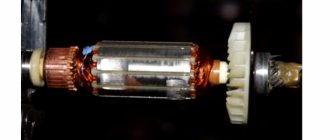
The electric motor armature consists of the following parts:
- a cylindrical element, which is formed by tightly connected stamped plates made of electrical steel with low silicon content, or from Armco low-carbon steel grades EA or EAA;
- the shaft on which the cylinder is mounted;
- phase coils, the windings of which are shifted relative to each other by an angle of 1200;
- slip rings mounted on the shaft, but electrically insulated both from it and from each other.
The armature on the rotary hammer is in mechanical contact with the gears of the rotary hammer gearbox, so to completely disconnect it, it is enough to disengage the assembly from the worm, which is located on the rotor shaft.
The check begins with an external inspection of the collector plates: they should not have traces of soot or scratches. In this case, the motor brushes are considered operational and cannot be replaced.
Slow rotation of the armature on the hammer drill may be caused by contamination of the bearing dust washer; in this case, it is removed from the housing and thoroughly washed with a technical solvent. Acceptable fluids are usually listed by the manufacturer in the manual for the hammer drill. Not only the outer surface, but also the inner surface of the protective washer should be cleaned.
Despite the fact that the outer winding of the armature also has dust protection, it is worth inspecting the condition of the winding cords, and you can use a regular vacuum cleaner to clean their surface.
The integrity of the collector is checked by a tester. According to the existing electrical diagram of the tool, all elements of the electrical circuit of the hammer drill are checked. If there is a short circuit, the armature needs to be replaced. For long-term use of a tool, the price of the issue is determined by the model of the hammer drill: it is possible that the warranty workshop does not accept hammer drills of a certain brand for repair, and a request for the required anchor model will have to be sent to the manufacturer’s warehouses.
If the unstable operation of the hammer drill was caused only by contamination of its moving parts, then after thorough cleaning, the unit is assembled in the reverse order. In this case, it is necessary to ensure that the contact of the gear with the gear worm is complete, and the dust ring completely covers the outer bearing housing.
How to determine the integrity of the stator without disassembling the hammer drill
To determine the integrity of the stator, you need to ring its windings, measure the winding resistance and insulation resistance.
Stator and rotor continuity diagram
To measure the winding resistance of a Makita hammer drill, you need to connect one end of the tester to the released brush holder, and the other to one of the ends of the electric plug. If the device does not show anything, change the other end of the plug. If the resistance is infinity, there is a break in the stator and it requires replacement or repair. Don’t forget, you can’t do without a circuit diagram of a Makita 2450,2470 rotary hammer.
READ Bosch Washing Machine Doesn't Spin Drum
Simple connection diagram for a commutator motor
If some kind of resistance is shown, it is important to measure its exact value. As a rule, the resistance of the stator winding of the Makita-2450 rotary hammer at a temperature of 20ºС is within 25 Ohms.
To understand in more detail why the armature commutator sparks and which brushes are better? The video will help you figure it out; at the end of the video review there are important tips on choosing brushes
Designs of anchors for rotary hammers of different types
An armature is a rotating unit of any asynchronous motor. Considering that during operation the hammer drill experiences significant resistance from the material it destroys, the loads on the rotor often reach extreme values. Sometimes they cause a significant decrease in armature speed, which leads to immediate failure of the electric motor.
The stability of the armature on a hammer drill from combustion is determined by its design. There are two types of rotary hammer anchors:
With wound rotor. With squirrel-cage rotor.
The short-circuited armature winding is formed by rods, which, when assembling the rotor, are placed in the grooves of its core. In this case, the ends of the rods are connected using a special rotor ring. There are no moving contacts in this design, which has a positive effect on the durability of the unit.
The disadvantage of an armature of this design is the limited starting torque, which, relative to hammer drills, requires a limitation on the intensity of use at the initial time after turning on the tool. Naturally, it is impossible to constantly remember this, because if you use the hammer drill inattentively, the durability of the engine with a squirrel-cage rotor will be low.
The problem is solved by installing electric motors with a squirrel-cage rotor on all rotary hammers. The number of poles of the armature winding in this case fully corresponds to the same parameters for the stator, and the contacts of each phase are brought into the external circuit through carbon-graphite brushes. Replacing brushes is a relatively simple process that can (for equipment not under warranty) be done independently. In other cases, it is worth using the services of specialists. Often the price for this type of service is associated with the need for static and dynamic balancing of the armature on a hammer drill, for which special technology and equipment are used.
If you want to learn about graphite brushes and their replacement, click on the link https://proinstrumentinfo.ru/grafitovye-shhyotki-dlya-elektroinstrumenta-tonkosti-vybora/
Repair or replacement? The choice is yours!
A handyman with electrical experience can repair the fittings on a drill with his own hands. Start with troubleshooting. In the event of a break or short circuit in the turns of the armature winding, the reason for the “silence” of the punch or the slow rotation of its rotor (accompanied by intense sparking around the perimeter) is easy to establish: a tester. Sparking, as well as an attempt to turn the shock valve in different directions, is the result of short circuiting of part of the turns in the winding. If the spark has the character of a single, but long-lasting spark, the cause is a damaged wire or poor contact with the commutator itself.
When checking, you should also check for the possibility of damage to the valve body. When measuring actual resistance values, the values obtained must be at least several ohms.
During development of a hammer drill, significant imbalance in the axis of rotation of the valve is possible during punch operation. This fault is diagnosed after the open winding is not open. To do this, connect the drill to the rheostat and gradually increase the voltage to the nominal voltage. If during diagnostics the tone of the electric motor changes and the armature oscillations increase, rotor balancing is necessary.
Since it is almost impossible to rewind the anchor at home, it is recommended to use the services of specialized workshops. The price of winding an armature on a rotary hammer for most models (from Bosch, DeWalt, Makita, etc.) depends on the power of the tool and its performance (home or professional). If the drive power does not exceed 1000 W, the service will cost 1000. 1200 rubles, for a drive up to 1500 W. 1500. 1600 rubles, and for more powerful rotating hammers. Up to 2500 rubles. Comprehensive repairs (for example, replacing a bearing) can cost 3500. 4000 rubles. In this case, fault diagnosis in most workshops is free.
Source
How to repair an anchor at home
A third of screwdriver failures occur due to the anchor. With everyday intensive operation, malfunctions can occur within the first six months, for example, if the brushes are not replaced in a timely manner. With gentle use, the screwdriver will last a year or more.
The anchor can be saved if the balance is not disturbed. If during operation of the device you hear an intermittent hum and there is strong vibration, then this is an imbalance. This anchor must be replaced. And the winding and commutator can be repaired. Small short circuits are eliminated. If a significant part of the winding is damaged, it can be rewound. Worn and badly damaged lamellas should be sharpened, extended or soldered. In addition, you should not undertake anchor repairs if you are unsure of your capabilities. It is better to replace it or take it to a workshop.
Collector groove
Over time, wear from the brushes forms on the commutator. To get rid of it, you need to:
- Grind the commutator using cutters for longitudinal grinding, that is, through cutters.
- We also need a reverse cone for centering on the bearing. Make a hole in it up to 8 mm.
- Since copper is malleable, adjust the machine to a speed of 600 to 1500 rpm.
- Primary feed in half divisions. When the cutter lightly touches the product, make a longitudinal groove of the entire collector. Based on the resulting shiny pattern, you will see the condition of the lamellas and all surface irregularities.
- If the collector is level, then the groove will be uniform.
- If there are holes, continue grooving until the surface is level.
- For the last pass, you need to move the cutter one-fourth from the division.
- To polish, take thousand-grit sandpaper and turn on the machine so that the armature rotates in the direction in which it rotates during operation.
Don't forget to clear the rotor of chips to prevent a short circuit.
Video on the topic
How to rewind an anchor
Before disassembling the armature, write down or sketch the direction of the winding. It can be left or right. To determine it correctly, look at the end of the armature from the commutator side. Wear gloves and take sharp wire cutters or a hacksaw. Remove the winding end parts. The collector needs to be cleaned, but it is not necessary to remove it. Carefully, without damaging the slot insulators, knock out the rods of the remaining parts of the winding using a hammer and metal chisel.
Video: Removing the winding
Using a needle file, without damaging the insulator film, remove the remaining impregnation. Count the conductors in the slot. Calculate the number of turns in the section and measure the diameter of the wire. Draw a diagram. Cut cardboard sleeves for insulation and insert them into the grooves.
Video: Winding left and right
After winding, weld the section leads to the collector cocks. Now check the winding with a short circuit tester and indicator. Proceed with impregnation.
Instructions for impregnation (taking into account the speed controller)
- After making sure that there are no problems, send the armature to the electric oven to warm up for better flow of the epoxy resin.
- After warming up, place the anchor on the table at an angle for better spreading over the wires. Apply resin to the frontal area and slowly rotate the anchor. Drip until glue appears on the opposite frontal part.
- Place the anchor horizontally and drip onto both frontal parts. Twist the anchor until it loses fluidity.
- Leave in a vertical position until complete polymerization.
At the end of the process, lightly grind the commutator. Balance the anchor using a dynamic balancer and an angle grinder. Now make the final grind on the bearing. It is necessary to clean the grooves between the lamellas and polish the collector. Make a final check for opens and shorts.
How to change brushes with a hammer, where are they?
The brushes of any power tool are part of the power circuit. And although brushes are the weakest point of commutator-type electric motors, they cannot be avoided, since they conduct current from the power source to the valve commutator.
The main reason for brush failure. Its abrasion during use. When the brush wears out and there is no contact with the commutator, the power circuit is interrupted and the tool stops working. In addition to this fault, there may also be a broken wire running from the terminal to the brush or a broken spring. But these are extremely rare breakdowns and can be eliminated without replacing the brushes, if the latter are in order.
READ Replacing Line on Trimmer Video Stihl Fs38
Types of brushes in rotary hammers:
- Graphites. They have a long service life, but due to the hardness of the graphite, their abrasion is not ideal and this has a negative effect on the commutator.
- Coal. Maintains excellent contact with the commutator, but due to the softness of graphite has a short service life.
- Carbon graphite. As the name suggests, it consists of a mixture of graphite and coal; perfect option.
When you need to replace your brush.
Typically, the supply of brushes in rotary hammers is designed for 80-120 hours of operation, but who will keep track of the operation of a home tool? In this regard, it is convenient to have a tool with a brush wear indicator or with an automatic shut-off function when the maximum wear is exceeded.
But even without these important features, you can determine that it's time to replace the brush:
Increased sparking in the collector area;
The tool does not work smoothly, periodically, as well as speed and power drop.
In these cases, you will need to obtain and inspect the brush assembly. If the defects described above are found, the brushes should be replaced. An additional condition when it is necessary to replace the brushes is that they are worn to a third of the nominal value (usually approximately 8 mm).
Please note the following: both brushes are ALWAYS replaced at the same time, even if one of them is fully functional.
The process of replacing punched brushes is simple and anyone can do it, especially those with power tool skills. The only thing is that not all models have the same approach to brush assembly. On some models you need to remove half the body (older models), while on others you only need to remove the back cover.
Some modern models have a special window covered with a plastic cover for replacing the brush assembly. In particular, these are some BOSCH models.
So basically the whole job of replacing brushes in a die is to find the location of the brush in your model, then carefully remove the brushes from there and carefully insert the new set back in.
After watching this video, you will understand the general working principle of replacing perforated brushes and, therefore, cope with the tool of your model.
Operating rules or how to protect the device from damage
To ensure long-term and efficient operation of an electric hammer drill, it is enough to follow a few simple rules. In particular:
- When working, it is not advisable to put too much pressure on the tool; at least this is not necessary, and moreover, with excessive pressure, the tool will fail faster.
- It is not permissible to operate the electric hammer drill in idle mode.
- When working with porous materials, it makes sense to turn off the impact mechanism. When working with particularly hard materials, it is advisable to use a lubricant.
- When working, especially for a long time, it is necessary to monitor the heating of the housing, especially in the place where the gearbox is installed. If there is noticeable heating, you must stop the work and wait until it cools down. Water cannot be used for cooling; its use may damage gearbox parts.
- Work with the tool should be carried out in the following mode - at least a 10-minute break after half an hour of work.
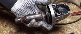
Bearing replacement
During troubleshooting, a common defect is increased play in the rotor bearings . To avoid big troubles, they should be replaced .
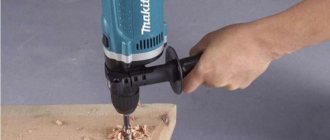
When replacing the rotor bearings in a DVT grinder at home, the following video uses any available means . The rotor is pressed out using a metal screwdriver rod and a wrench supported by a boss inside the gearbox housing. This action is not very convenient to perform, but ultimately it achieves its goal.
In the next video, of unscrewing the fastener of the fixing plate to the bearing gear housing through the technological holes in the impeller was further developed Since the impeller is plastic, it is effective to burn holes with a heated rod, such as a nail. To maintain balance, it is recommended to make two holes at once .