Anchor device
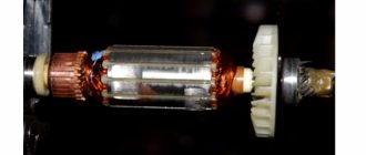
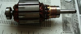
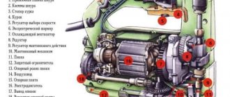
The armature (rotor) together with the stator are included in the design of an asynchronous commutator motor used as an electric motor in angle grinders. If the stator is made in the form of a stationary element, then the rotor just rotates , transmitting torque to the spindle of the angle grinder. Therefore, a shaft with bearing supports at the ends best suits the tasks performed by the rotor.
A metal core with grooves is fixed on the shaft , into which copper wire is laid according to a special winding pattern. The coils thus formed create, together with the stator coils, an electromagnetic field that causes the rotor to rotate.
Scheme of operation of the grinder. Source
A collector is installed on the shaft , which actually gives the name to this type of electric drive. It is a set of copper plates (lamellas) to which the ends of the armature coils are soldered. The stator brushes come into contact with the commutator , which creates a closed electrical circuit into which all the components of the electrical part of the angle grinder are connected.
Features of the asynchronous motor of the angle grinder
In fact, all electrical appliances used in everyday life use an asynchronous electronic motor. The fundamental advantage of this type of motor is that when the load on it changes, the speed does not change. This means that if, for example, you cut stone for a long time without stopping with a household grinder, there will be no noticeable signs of motor overload. The disk rotation speed will be constant, the sound will be monophonic. Only the temperature will change, but this may not be visible if your hands are wearing gloves.
If you are not careful, an advantage can turn into a disadvantage. Asynchronous motors are very sensitive to overheating; a significant increase in operating temperature entails melting of the insulation on the rotor windings. At first, the motor will work intermittently, and later - when an inter-turn short circuit occurs - the engine will stop completely. If you overheat the grinder’s engine a couple of times, it’s more likely that the anchor will melt. In addition, the high temperature causes the contacts connecting the wires of the primary winding to the collector to become unsoldered, which leads to an interruption in the supply of electronic current.
READ Angle grinder Bosch 125 with adjustment
Replacing bearings on an angle grinder. How to remove an anchor
Replacing the anchor begins with disassembling the angle grinder. The following steps are taken:
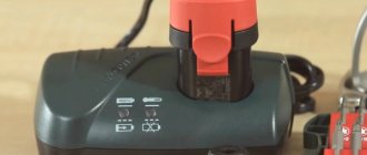
- Use a screwdriver to unscrew the brush units from both sides. The brushes are removed.
How to check the rotor for serviceability
Multimeter Zubr. Photo 220Volt
The scope of repair work can be determined by competent diagnosis of rotor damage. The specifics of the formation of defects, which most often appear when the angle grinder overheats during prolonged operation at high loads, allows you to determine them visually . Burnt electrical insulation leaves charring marks in places where the coils are damaged or on the commutator lamellas. Broken wires and swollen collector lamellas can also be seen after a careful external inspection.
If a visual inspection fails to identify malfunctions or doubts arise, diagnostics are carried out by checking the electrical circuit using instruments. Here, a breakdown to the housing or a wire break can be detected with a multimeter , and an interturn short circuit with an indicator of short-circuited turns or on a special device for checking the presence of a short circuit of the turns.
Rewinding the Drill Anchor with Your Hands
DIY drill repair
Some spare parts (switch, rotor, stator, brushes, bearings, etc.) for more popular models are bought here (but it’s better to buy through an online store, because in a regular store of this network you will like the price higher).
Replacing brushes
. The most common type of breakdown is wear of the motor brushes, which can be replaced yourself at home. Sometimes, brushes can be replaced without disassembling the drill body. For some models, it is enough to unscrew the plugs from the installation windows and install new brushes. For other models, replacement requires disassembling the housing; in this case, you must carefully remove the brush holders and remove the worn brushes from them.
Brushes are sold at all normal power tool stores, and often an extra pair of brushes is included with a new electric drill.
Don't wait for the brushes to wear down to their minimum size. This risks increasing the gap between the brush and the collector plates. As a result, increased sparking occurs, the collector plates become very hot and may move away from the base of the collector, which will lead to the need to replace the armature.
You can determine the need to replace brushes by increased sparking, which can be seen in the ventilation slots of the housing. The second way to determine this is the random jerking of the drill during operation.
Power cord
. The cord is checked with an ohmmeter, one probe is connected to the contact of the power plug, the other to the core of the cord. Lack of resistance indicates a break. In this case, repairing the drill comes down to replacing the power cord.
Electric motor diagnostics
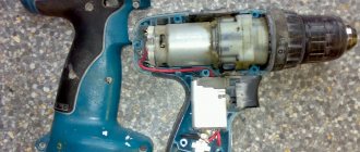
. In second place, in terms of the number of drill breakdowns, can be placed the malfunction of engine components and, most often, the armature. Failure of an armature or stator occurs for two reasons. improper operation and poor-quality coil wire. World-famous manufacturers use expensive coil wire with double insulation with heat-resistant varnish, which significantly increases the reliability of engines. Accordingly, in cheap models the quality of insulation of the winding wire leaves much to be desired. Improper operation comes down to frequent overloading of the drill or prolonged operation without breaks to cool the engine. Repairing a drill with your own hands by rewinding the armature or stator, in this case, is impossible without special tools. Only complete replacement of the element (exclusively experienced repairmen will be able to rewind the armature or stator with their own hands).
To replace the rotor or stator, it is necessary to disassemble the housing, disconnect the wires, brushes, remove the drive gear if necessary, and remove the entire motor along with the support bearings. Replace the faulty element and install the engine in place.
READ DIY Wind Generator From a Screwdriver Engine
An armature malfunction can be determined by a characteristic smell, an increase in sparking, and the sparks have a circular motion in the direction of movement of the armature. Pronounced burnt windings can be seen upon visual inspection. But if the engine power has dropped, but there are no signs described above, then you should resort to the help of measuring instruments. ohmmeter and megohmmeter.
The windings (stator and armature) are subject to only three types of damage. interturn electrical breakdown, breakdown to the housing (magnetic circuit) and winding breakage. A breakdown to the housing is determined quite simply; it is enough to touch any winding output and magnetic circuit with the probes of a megohmmeter. A resistance of more than 500 MΩ indicates no breakdown. It should be taken into account that measurements should be carried out with a megger with a measuring voltage of at least 100 volts. By taking measurements with a simple multimeter, it is impossible to accurately determine that there is definitely no breakdown, but you can determine that there is definitely a breakdown.
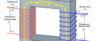
It is quite difficult to determine the interturn breakdown of the armature, unless, of course, it is visible visually. To do this, you can use a special transformer, which has only a primary winding and a break in the magnetic circuit in the form of a trench for installing an armature into it. At the same time, the anchor
with its core become a secondary winding. Rotating the armature so that the windings alternate in operation, we apply a thin metal plate to the armature core. If the winding is short-circuited, the plate begins to rattle strongly, and the winding heats up noticeably.
Repair and rewinding of the armature of the HITACHI M 8V2 router. The first film.
Repair - rewind
milling cutter HITACHI M 8V2.
It is shown in detail HOW to rewind the armature
of the HITACHI M 8V2 router. Movie .
Rewinding the vacuum cleaner armature
.
Often, an interturn short circuit is detected in visible areas of the wire or armature bar: the turns may be bent, crumpled (i.e., pressed against each other), or there may be some conductive particles between them. If so, then it is necessary to eliminate these short circuits by correcting bruises in the tire or removing foreign bodies, respectively. Also, a short circuit can be detected between adjacent collector plates.
You can determine whether the armature winding is broken if you connect a milliammeter to the adjacent armature plates and gradually turn the armature. In whole windings a certain identical current will appear; a broken winding will show either an increase in current or its complete absence.
A break in the stator windings is determined by connecting an ohmmeter to the disconnected ends of the windings; the absence of resistance indicates a complete break.
Speed controller and reverse
. The presence of voltage at the input terminals of the power button and absence at the output terminals indicates a malfunction of the contacts or components of the speed controller circuit. You can disassemble the button by carefully picking up the latches of the protective casing and pulling it off the button body. A visual inspection of the terminals will allow you to judge their performance. Blackened terminals are cleaned of carbon deposits with alcohol or fine sandpaper. Then the button is reassembled and checked for contact; if nothing has changed, then the button with the regulator must be replaced. The speed controller is made on a substrate and is completely filled with an insulating compound, so it cannot be repaired. Another typical malfunction of the button is the erasure of the working layer under the rheostat slider. The easiest way out. replacing the entire button.
READ Do-It-Yourself Potato Planter for Motoblock
Repairing a drill button with your own hands is only possible if you have certain skills. It is important to understand that after opening the case, many switching parts will simply fall out of the case. This can be prevented only by smoothly lifting the cover initially and sketching the location of the contacts and springs.
The reverse device (if it is not located in the button body) has its own changeover contacts, and therefore is also susceptible to contact loss. The disassembly and cleaning mechanism is the same as the buttons.
When purchasing a new speed controller, you should make sure that it is designed for the power of the drill, so with a drill power of 750W, the regulator must be designed for a current of more than 3.4A (750W/220V=3.4A). And by the way, the regulator of the drill in the photo is not original, and in order for it to fit into the body, the lower part of the trigger was cut off.
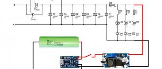
The wiring diagram, and in particular the drill button connection diagram, may differ in different models. The simplest diagram, and best demonstrating the principle of operation, is the following. One lead from the power cord is connected to the speed controller.
To avoid confusion, it is important to understand what the speed controller and the reverse control device are. these are two different parts that often have different housings.
The only wire coming out of the speed controller is connected to the beginning of the first stator winding. If there were no reversing device, the end of the first winding would be connected to one of the rotor brushes, and the second rotor brush would be connected to the beginning of the second stator winding. The end of the second stator winding leads to the second wire of the power cord. That's the whole scheme.
Changing the direction of rotation of the rotor occurs when the end of the first stator winding is connected not to the first, but to the second brush, while the first brush is connected to the beginning of the second stator winding .
This switching occurs in the reverse device, so the rotor brushes are connected to the stator windings through it. This device may have a diagram showing which wires are connected internally.
READ DIY Drill Vise
Black wires lead to the rotor brushes (let the 5th contact be the first brush, and let the 6th contact be the second brush), gray. to the end of the first stator winding (let there be the 4th contact) and the beginning of the second (let there be the 7th contact). When the switch is in the position shown in the photo, the end of the first stator winding with the first rotor brush (4th with 5th), and the beginning of the second stator winding with the second rotor brush (7th with 6th) are closed. When switching the reverse to the second position, the 4th is connected to the 6th, and the 7th to the 5th.
The design of the electric drill speed controller provides for connecting a capacitor and connecting both wires coming from the outlet to the controller. The diagram in the figure below, for better understanding, is slightly simplified: there is no reverse device, the stator windings to which the wires from the regulator are connected are not yet shown (see diagrams above).
In the case of the electric drill shown in the photo, only two lower contacts are used: the far left and the far right. There is no capacitor, and the second wire of the power cord is connected directly to the stator winding.
Read about the principle of operation of the speed controller in the article about the device of a drill.
Gearbox
. The presence of extraneous sounds, grinding and jamming of the cartridge indicates a malfunction of the gearbox or gear shift mechanism, if any. In this case, it is necessary to inspect all gears and bearings. If worn splines or broken teeth are found on the gears, then a complete replacement of these elements is necessary.
Bearings are checked for suitability after removing them from the armature axis or drill body using special pullers. While holding the inner race with two fingers, you need to rotate the outer race. Uneven slippage of the race or rustling noise when turning indicates the need to replace the bearing. A bearing replaced at the wrong time will lead to jamming of the armature, or, in the best case, the bearing will simply turn in the seat.
Replacing the drill chuck
. The chuck is subject to wear, namely the clamping jaws, due to dirt and abrasive residues of building materials getting into it. If the cartridge needs to be replaced, it is necessary to unscrew the retaining screw inside the cartridge (left-hand thread) and unscrew it from the shaft.
Source
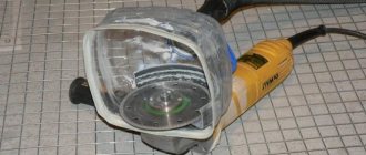
How to recover
In the following video, the author tries to eliminate a manufacturing defect on a model from a “Chinese” manufacturer. A large gap between the inner race of the bearing and the seat on the shaft is the reason for the rapid failure of the angle grinder. The author proposes to restore the required shaft size using welding surfacing technology . Of course, whether such a measure is effective is questionable. Such a bearing assembly will not work for a long time, but in some cases it may work as a way out.
How to check with a multimeter
Set the resistance to 200 ohms. Connect the probes of the device with two adjacent lamellas. If the resistance is the same between all adjacent plates, then the winding is working. If the resistance is less than 1 ohm and very close to zero, there is a short circuit between the turns. If the resistance is two or more times higher than average, then there is a break in the winding turns. Sometimes when there is a break, the resistance is so great that the device goes off scale. On an analog multimeter, the arrow will go all the way to the right. But digital won’t show anything.
Video: how the check is carried out
If you don't have a tester, use a 12-volt light bulb with up to 40 watts.
How to check the rotor of an angle grinder using a light bulb
This procedure is similar to diagnostics with a multimeter.
How to fix, repair
The rotor, unlike the stator, the main element of which is the winding, has a more complex structure . In addition to the coils wound into the grooves of the core, its assembly includes bearing units, a collector, a fan and the shaft itself. This increases the number of possible faults , which means it is somewhat more difficult to repair the rotor than the stator.
Repair of rotor windings
The following video describes rotor repair for the most common electrical fault - winding damage . The author briefly describes the sequence of operations for repairing rotor windings: from diagnostics to rewinding and impregnation .
Important: the author points to a control check by instruments of the correct execution of each operation where necessary.
Collector repair
The defect that is corrected in the next video, namely the separation of the commutator lamellas, does not occur so often with intact rotor windings. However, the author brilliantly performs it at home. Instead of missing lamellas, new ones are made from copper wire using the cold forging method.
After soldering and gluing the lamellas, all sagging is removed using metalwork , and the final finishing of the collector surface is carried out using the original method proposed by the author. It is not always possible to find a lathe at home, so the anchor is assembled at its intended destination (in a grinder), where instead of brushes, a tool for processing the commutator lamellas is installed.
It consists of wooden blocks adjusted to size, onto which sanding paper is attached. The processing force is created by tightening the plug that presses the bar to a certain amount. The rotor is driven through the spindle by another grinder. Thus, by changing the sanding paper several times, a perfectly smooth and polished surface of the collector is achieved after replacing the lamellas.
Replacing the fan impeller
, the hub of a metal impeller on the rotor after a foreign object hit it. The author found a way out of the situation by assembling a new impeller from a broken one and another taken from a burnt-out hammer drill rotor. Using a homemade device made from a drill and a vice, the excess elements were cut off with a sharp knife from the impeller of a hammer drill (plastic) mounted on the rotor, that is, only the hub remained. Next, the damaged impeller was riveted onto the hub. When rotating, using a drive, a drill, bearing support in a vice and a file, the required radial and axial runout was set on the assembled new impeller.
The rotor sparks, the reason, how to fix it
The main reasons causing increased sparking during operation of the angle grinder.
- The brushes are worn out. They should be replaced, sometimes together with the brush holder and the preload spring to achieve the result.
- Breaks, short circuits in the rotor winding. Replacing the armature or rewinding a new winding will help eliminate strong sparking. In the video, replacing the armature and brushes creates normal conditions for the functioning of the brush-collector assembly.
- Faults in the stator winding can cause sparking. Here, by analogy with an armature, the stator winding or the stator itself should be replaced.
- Accumulation of graphite dust on or between the lamellas . Regular cleaning of the lamellas with sandpaper and removal of graphite between them will make it impossible to create additional conditions for a spark to occur.
- The brushes may be installed incorrectly in relation to the commutator surface and, as a result, conditions are created for the formation of a large amount of graphite dust. This can be eliminated by straightening the misaligned brushes.
- When overheated, carbon deposits form on the commutator, which creates conditions for poor contact of the brushes with the lamellas and increased sparking. It is necessary to clean the surface of the commutator with fine-grain sandpaper, after which polishing on a felt wheel will make the brush-commutator unit work effectively.
- Mechanical violations caused by deviations from the technical requirements for the design of the angle grinder. Most of them can be eliminated, as in the video, for example, by turning them on a lathe.
How to repair an anchor at home
A third of screwdriver failures occur due to the anchor. With everyday intensive operation, malfunctions can occur within the first six months, for example, if the brushes are not replaced in a timely manner. With gentle use, the screwdriver will last a year or more.
The anchor can be saved if the balance is not disturbed. If during operation of the device you hear an intermittent hum and there is strong vibration, then this is an imbalance. This anchor must be replaced. And the winding and commutator can be repaired. Small short circuits are eliminated. If a significant part of the winding is damaged, it can be rewound. Worn and badly damaged lamellas should be sharpened, extended or soldered. In addition, you should not undertake anchor repairs if you are unsure of your capabilities. It is better to replace it or take it to a workshop.
Collector groove
Over time, wear from the brushes forms on the commutator. To get rid of it, you need to:
- Grind the commutator using cutters for longitudinal grinding, that is, through cutters.
- We also need a reverse cone for centering on the bearing. Make a hole in it up to 8 mm.
- Since copper is malleable, adjust the machine to a speed of 600 to 1500 rpm.
- Primary feed in half divisions. When the cutter lightly touches the product, make a longitudinal groove of the entire collector. Based on the resulting shiny pattern, you will see the condition of the lamellas and all surface irregularities.
- If the collector is level, then the groove will be uniform.
- If there are holes, continue grooving until the surface is level.
- For the last pass, you need to move the cutter one-fourth from the division.
- To polish, take thousand-grit sandpaper and turn on the machine so that the armature rotates in the direction in which it rotates during operation.
Don't forget to clear the rotor of chips to prevent a short circuit.
Video on the topic
How to rewind an anchor
Before disassembling the armature, write down or sketch the direction of the winding. It can be left or right. To determine it correctly, look at the end of the armature from the commutator side. Wear gloves and take sharp wire cutters or a hacksaw. Remove the winding end parts. The collector needs to be cleaned, but it is not necessary to remove it. Carefully, without damaging the slot insulators, knock out the rods of the remaining parts of the winding using a hammer and metal chisel.
Video: Removing the winding
Using a needle file, without damaging the insulator film, remove the remaining impregnation. Count the conductors in the slot. Calculate the number of turns in the section and measure the diameter of the wire. Draw a diagram. Cut cardboard sleeves for insulation and insert them into the grooves.
Video: Winding left and right
After winding, weld the section leads to the collector cocks. Now check the winding with a short circuit tester and indicator. Proceed with impregnation.
Instructions for impregnation (taking into account the speed controller)
- After making sure that there are no problems, send the armature to the electric oven to warm up for better flow of the epoxy resin.
- After warming up, place the anchor on the table at an angle for better spreading over the wires. Apply resin to the frontal area and slowly rotate the anchor. Drip until glue appears on the opposite frontal part.
- Place the anchor horizontally and drip onto both frontal parts. Twist the anchor until it loses fluidity.
- Leave in a vertical position until complete polymerization.
At the end of the process, lightly grind the commutator. Balance the anchor using a dynamic balancer and an angle grinder. Now make the final grind on the bearing. It is necessary to clean the grooves between the lamellas and polish the collector. Make a final check for opens and shorts.
The peculiarity of the winding for angle grinders with adjustable speed is that the rotor is wound with a power reserve. Current density affects the number of revolutions. The wire cross-section is too high and the number of turns is too low.
How to change
Replacing the rotor with a new one is often used when repairing angle grinders. So, in the case of a burnt winding, not everyone is able to rewind it efficiently. However, to achieve a successful result with this repair method, you should know the layout design and electrical circuit of the model being repaired.
In the following video, the author demonstrates replacing the anchor on a Makita model angle grinder. The design of this grinder allows assembly and disassembly without any problems. In this case, it was necessary to use an impact tool (hammer) only to press the rotor out with light blows from the lower race of the bearing located in the gear housing cover.
Replacing the anchor in a small angle grinder of the Interskol model has its own characteristics, which are shown in the following video. Here, a metal plate is included in the rotor assembly unit, with the help of which two screws secure the rotor to the gearbox housing. By unscrewing/tightening these two screws, you can completely disassemble/assemble the entire rotor assembly along with all its components.
When replacing the rotor on a large angle grinder, model Interskol 230, in the following video, the author shares his experience of removing the rotor from the gearbox housing. The design of the gearbox housing (the presence of ribs) does not make it possible to fully use the wrench to unscrew the clamping drive gear of the nut. Therefore, it is used only as a stopper to fix the edges of the nut. The rotor core, wrapped in canvas (in order to protect it from damage), is inserted into a vice. In this position, the gearbox rotates in the direction of unscrewing the nut, and the rotor mount is released.
A Bosch model grinder fell into the hands of an experienced craftsman (next video) after an amateurish repair by the previous owner. Analysis of rotor damage leads to the conclusion that it needs to be replaced. A new rotor after grooving the commutator is quite capable of replacing a failed one. After replacement, the Bosch model angle grinder operates normally.
How to clean
The condition of the commutator significantly affects the service life of the brushes, will significantly reduce sparking, which will make the grinder work at parameters close to the nominal ones. Why is it necessary to clean it regularly ?
One of the options for collector cleaning technology is shown in the following video. Available consumables and tools are:
- emery cloth with abrasive numbers 1000 and 2000;
- felt circle with a cylindrical shank;
- screwdriver or drill;
- paste GOI;
- needle;
- needle file;
- small brush.
The technology of the operations is quite simple. Important: do not forget to chamfer the lamellas, which is what the needle file is for.
How to choose
When replacing a new rotor, it must correspond to the parameters of the previous faulty one. If on branded grinders (Makita, Bosch and others) the rotor in specialized stores can be easily selected by the name of the model, then for a “Chinese” grinder there is a big risk of making a mistake.
Recommendations on how to choose and which sizes are the main ones to search for are offered in the videos below.
The first main dimension is the outer diameter of the rotor core. Other important parameters : bearing diameters, total rotor length, linear distance between the inner sides of the bearings. All specified dimensions can be measured with a caliper . Usually these parameters are enough to find the required rotor on online store sites. Important: When searching, you should consider the mounting option for the pinion gear (key, splines, or smooth fit with snap ring in place).
By size, for Bosch
When selecting an anchor for a Bosch angle grinder on online store sites, you must, in addition to the model, know the part number according to the catalog . It is a 10-digit code . The site has a section “diagrams and details”, where you can go by clicking on the name of the Bosch model and enter the code. The diagram that opens contains the desired anchor.
If there are difficulties in having data for searching, you should take measurements from the anchor to be replaced. Next, in the “search” section, enter the following information:
- manufacturer, for example, Bosch;
- core outer diameter;
- nominal landing diameter of the drive gear, its type;
- linear dimensions of the rotor.
If there are a sufficiently large number of options, additional parameters are introduced: core length, distance between bearings, and others.