General information
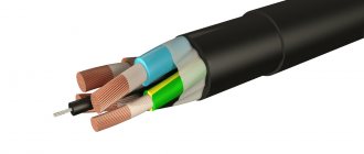
Transformer welding machines are relatively inexpensive and easy to repair due to their simple design. However, they are heavy and sensitive to supply voltage (U). When U is low, it is impossible to carry out work, since significant changes in U occur, as a result of which household appliances may fail. In the private sector, there are often problems with power lines, since in the former CIS countries most power lines require cable replacement.
The electrical cable consists of twists, which often oxidize. As a result of this oxidation, an increase in the resistance (R) of this twist occurs. Under significant load, they heat up, and this can lead to overload of power lines and transformer substation. If you connect an old-style welding machine to an electricity meter, then when U is low, the protection will be triggered (“knock out” the machines). Some people try to connect the welder to the electricity meter, breaking the law.
Such a violation is punishable by a fine: electricity is consumed illegally and in large quantities. In order to make work more comfortable - not to depend on U, not to lift heavy objects, not to overload power lines and not to break the law - you need to use an inverter-type welding machine.
Manufacturing of transformer and choke
The main task of the transformer is to convert the voltage of high-frequency current with sufficient strength. The cores can be used model Ш20×208, in the amount of two pieces. You can create the gap between the parts yourself using plain paper. The winding is made with your own hands, with a copper strip 40 mm wide, the thickness should be at least 0.2 mm. Thermal insulation is achieved using cash register thermal tape; it demonstrates good wear resistance and strength.
How to make a transformer for an inverter
The use of copper wire when winding the core is unacceptable, because it forces current onto the surface of the device. To remove excess heat, a fan or cooler from the computer power supply, as well as a radiator, are used.
The inverter unit is responsible for the throughput of the electric arc through the use of transistors and chokes.
For a stable welding process, it is recommended to use several transistors in a parallel circuit rather than one more powerful element.
Due to this, the output current is stabilized; during the process of inverter welding with your own hands, the device produces less noise.
Homemade choke
Capacitors connected in series are responsible for several functions:
- Resonant emissions are minimized.
- Ampere losses due to the design features of transistors, which open much faster than they close.
Homemade transformer as the basis for an inverter
Transformers get very hot due to the large volume of passing current. Radiators and fans are used to control the temperature. Each element is mounted on a radiator made of heat-dissipating material; if it is possible to install one powerful cooler, this will reduce assembly time and simplify the design.
Device and principle of operation
The welding inverter is designed so that it is suitable for both home use and enterprise use. With small dimensions, it is capable of ensuring a stable burning of the welding arc and even using a welding current that is significantly higher than that of an ordinary welding machine. It uses high-frequency current to generate a welding arc and is an ordinary switching power supply (the same as a computer one, only with higher current), which makes the circuit of the welding machine simple.
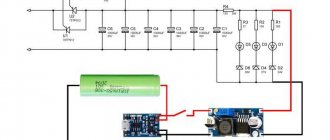
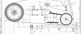
The basic principles of its operation are as follows: input voltage rectification; conversion of rectified U into high-frequency alternating current using transistor switches and further rectification of alternating U into high-frequency direct current (Figure 1).
Figure 1 - Schematic design of an inverter-type welder.
When using high-power key transistors, direct current is converted, which is rectified using a diode bridge into high-frequency current (30..90 kHz), which makes it possible to reduce the dimensions of the transformer. A diode rectifier allows current to flow in only one direction. The negative harmonics of the sinusoid are “cut off”.
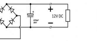
But the rectifier output produces a constant U with a pulsating component. To convert it into a permissible direct current in order to ensure the correct operation of key transistors operating only on direct current, a capacitor filter is used. A capacitor filter is one or more high-capacity capacitors, which can significantly smooth out ripples.
The diode bridge and filter make up the power supply for the inverter circuit. The input of the inverter circuit is made using key transistors that convert DC U into high-frequency AC (40..90 kHz). This transformation is needed to power a pulse transformer, the output of which produces a high-frequency current of low U. A high-frequency rectifier is powered from the outputs of the transformer, and a high-frequency direct current is generated at the output.
The device is not very complicated, and any inverter welder can be repaired. In addition, there are many schemes by which you can make a homemade inverter for welding work.
Creating a power supply
It is very important to correctly make a transformer for the power supply. It will provide a stable voltage supply . The transformer is wound on ferrite 7x7 wide , a total of 4 windings are formed:
- primary (100 turns of wire with a diameter of 0.3 mm)
- first secondary (15; 1 mm)
- second secondary (15; 0.2 mm)
- third secondary (20; 0.3 mm)
First you need to make the first winding and insulate it with fiberglass. A layer of shielding wire needs to be wound onto it; its turns should be placed in the same direction as the turns of the winding itself.
Do the rest of the windings in the same way, remembering to insulate them from each other.
The main task of the inverter is to convert alternating current into direct current. For this purpose, diodes installed according to the “oblique bridge” scheme are used. It is also necessary to select suitable resistors for the electrical circuit.
Read also: Device for making knives with your own hands
According to this scheme, it is worth assembling this block:
In such a circuit, the diodes get very hot, so they simply need to be mounted on radiators. Cooling elements from various devices can be used as radiators. Attach the diodes to two radiators, the upper part through the mica spacer to one, the lower part through thermal paste to the second.
The diode leads should be directed in the same direction as the transistor leads. The wires connecting them should be no longer than fifteen centimeters. Using welding, attach a sheet of metal to the housing between the power supply and the inverter unit.
Homemade welding machine
Assembling an inverter for welding is easy, since there are many schemes. It is possible to make welding from a computer power supply and knock down a box for it, but you will end up with a low-power welder. Details about creating a simple inverter from a computer power supply for welding can be found on the Internet. An inverter for welding using a PWM controller such as UC3845 is extremely popular. The microcircuit is flashed using a programmer, which can only be purchased at a specialized store.
Inverter manufacturing
Before starting the manufacture of a high-frequency transformer for the inverter, it is necessary to make a getinaks board, guided by Scheme 2. The transformer is made on a magnetic core of the “Ш20х28 2000 NM” type with an operating frequency of 41 kHz. To wind it (I winding), it is necessary to use copper sheet with a thickness of 0.3..0.45 mm and a width of 35..45 mm (the width depends on the frame). Need to do:
- 12 turns (cross-sectional area (S) about 10..12 sq. mm.).
- 4 turns for the secondary winding (S = 30 sq. mm.).
A high-frequency transformer cannot be wound with an ordinary wire due to the skin effect. Skin effect is the ability of high-frequency currents to be forced onto the surface of a conductor, thereby heating it. The secondary windings should be separated by fluoroplastic film. In addition, the transformer must be properly cooled.
The choke is made on a magnetic core of type “Ш20×28” made of 2000 NM ferrite with S of at least 25 sq. mm.
The current transformer is made on two rings of the “K30×18×7” type and is wound with copper wire. Winding l is threaded through the ring part, and winding II consists of 85 turns (d = 0.5 mm).
Scheme 2 - DIY inverter welding machine diagram (inverter).
After successfully manufacturing a high-frequency transformer, you need to install radio elements on a printed circuit board. Before soldering, treat the copper tracks with tin; do not overheat the parts. List of inverter elements:
- PWM controller: UC3845.
- MOSFET transistor VT1: IRF120.
- VD1: 1N4148.
- VD2, VD3: 1N5819.
- VD4: 1N4739A at 9 V.
- VD5-VD7: 1N4007.
- Two VD8 diode bridges: KBPC3510.
- C1: 22 n.
- C2, C4, C8: 0.1 µF.
- C3: 4.7 n and C5: 2.2 n, C15, C16, C17, C18: 6.8 n (only use K78−2 or SVV-81).
- C6: 22 microns, C7: 200 microns, C9-C12: 3000 microns at 400 V, C13, C21: 10 microns, C20, C22: 47 microns at 25 V.
- R1, R2: 33k, R4: 510, R5: 1.3 k, R7: 150, R8: 1 at 1 W, R9: 2 M, R10: 1.5 k, R11: 25 at 40 W, R12, R13 , R50, R54: 1 k, R14, R15: 1.5 k, R17, R51: 10, R24, R25: 30 at 20W, R26: 2.2 k, R27, R28: 5 at 5W, R36, R46- R48, R52, R42-R44 - 5, R45, R53 - 1.5.
- R3: 2.2 k and 10 k.
- K1 for 12 V and 40A, K2 - RES-49 (1).
- Q6-Q11:IRG4PC50W.
- Six IRF5305 MOSFET transistors.
- D2 and D3: 1N5819.
- VD17 and VD18: VS-HFA30PA60CPBF; VD19-VD22: VS-HFA30PA60CPBF.
- Twelve Zener diodes: 1N4744A.
- Two optocouplers: HCPL-3120.
- Inductor: 35 microns.
DIY inverter assembly
For a homemade inverter device, you need to choose a reliable housing or make it yourself, using sheet metal with a thickness of at least 4 mm. As a base on which the welding inverter transformer will be mounted, you can use a getinax sheet with a thickness of at least 0.5 cm. The transformer itself is mounted on such a base using brackets that you can make yourself from copper wire with a diameter of 3 mm.
Factory made sliding housing
To create electronic circuit boards for the device, you can use foil PCB with a thickness of 0.5–1 mm. When installing magnetic cores that will heat up during operation, it is necessary to provide gaps between them necessary for free air circulation.
To automatically control the operation of the welding inverter, you will need to purchase and install a PWM controller in it, which will be responsible for stabilizing the welding current and voltage. To make it convenient for you to work with your homemade device, you need to install controls in the front part of its body. These elements include a toggle switch for turning on the device, a variable resistor knob with which the welding current is regulated, as well as cable clamps and signal LEDs.
Example of inverter front panel layout
Basic recommendations
Before assembly, you need to carefully familiarize yourself with the inverter welding diagram and purchase everything necessary for manufacturing: buy radio components in specialized radio stores, find suitable transformer frames, copper sheet and wire, think about the design of the housing. Planning the work greatly simplifies the assembly process and saves time. When soldering radio components, you should use a soldering station (induction with a hair dryer) to avoid possible overheating and failure of radio elements. You must also follow safety rules when working with electricity.
AC welder
This is the most common type of metal welding machine. It is easy to make at home and is easy to use. But the main disadvantage of the device is the large mass of the step-down transformer, which is the basis of the unit.
For home use, it is enough that the device produces a voltage of 60 V and can provide a current of 120-160 A. Therefore, for the primary, to which a 220 V household network is connected, you will need a wire with a cross-section of 3 mm2 to 4 mm2. But the ideal option is a conductor with a cross section of 7 mm2. With such a cross-section, voltage drops and possible additional loads will not be a problem for the device. It follows from this that the secondary requires a conductor 3 mm in diameter. If we take an aluminum conductor, then the calculated cross-section of the copper conductor is multiplied by a factor of 1.6. For the secondary you will need a copper busbar with a cross-section of at least 25 mm2
It is very important that the winding conductor is covered with rag insulation, since traditional PVC sheathing melts when heated, which can cause an inter-turn short circuit.
If you do not find a wire with the required cross-section, you can make it yourself from several thinner conductors. But this will significantly increase the thickness of the wire and, accordingly, the dimensions of the unit.
First of all, the base of the transformer is manufactured - the core. It is made from metal plates (transformer steel). These plates should have a thickness of 0.35-0.55 mm. The pins connecting the plates must be well insulated from them. Before assembling the core, its dimensions are calculated, that is, the dimensions of the “window” and the cross-sectional area of the core, the so-called “core”. To calculate the area, use the formula: S cm2 = a x b (see figure below).
But from practice it is known that if you make a core with an area of less than 30 cm2, then with such a device it will be difficult to obtain a high-quality seam due to a lack of power reserve. Yes, and it will heat up very quickly. Therefore, the cross-section of the core must be at least 50 cm2. Despite the fact that the weight of the unit will increase, it will become more reliable.
To assemble the core, it is better to use L-shaped plates and place them as shown in the following figure until the thickness of the part reaches the required value.
Upon completion of assembly, the plates must be fastened together (at the corners) with bolts, then cleaned with a file and insulated with fabric insulation.
Now you can start winding the transformer.
- First of all, you should wind the primary. To make it you will need to make 215 turns.
- It is recommended to make a branch at turns 165 and 190. To do this, you need to attach a PCB plate to the top of the transformer. All branches are secured to it with bolts. But they should be marked next to them. For example, near the first wire you should write “Common”, near the 2nd tap - “165 turns”, near the 3rd - “190 turns” and near the 4th - “215 turns”. In the future, this will allow you to regulate the current strength. If it is necessary to increase the current strength, then a winding with fewer turns is selected, and vice versa.
- Next, a secondary winding is made, consisting of 70 turns.
One nuance should be taken into account: the ratio of turns on the core should be 40% to 60%. This means that on the side where the primary is located there should be a smaller number of secondary turns. Due to this, when welding begins, the winding with more turns will be partially switched off due to the occurrence of eddy currents. At the same time, the current strength will increase, which will have a positive effect on the quality of the seam.
When the winding of the transformer is completed, the network cable is connected to the common wire and to the 215-turn branch. Welding cables are connected to the secondary winding. After this, the contact welding machine is ready for use.