What types of bore gauges are there?
There are two main types of bore gauges: micrometric and indicator.
Micrometric bore gauges (NM)
They are used for absolute measurements. By design, a micrometer bore gauge is a screw with a rigidly fixed drum and a stem with a measuring tip.
Photo No. 1: micrometric bore gauge
The measurement accuracy reaches 0.01 mm. Instruments are stored in cases that protect the instruments from contamination and mechanical damage.
Bore indicator gauges (NI)
Designed for relative measurements. By design, indicator bore gauges consist of two elements: measuring parts and indicator heads with clock dials.
Photo No. 2: indicator bore gauge
The division value is 0.01 mm.
Design and device of an indicator bore gauge
Indicator bore gauges are used to measure internal distances in a relative manner. The abbreviation NI is used to designate them, and the produced models differ from each other in the measurement range. The devices consist of an extension rod with a rod inside, a dial indicator with a scale, as well as a direct working part called a tip.
In instruments of the NI-10 and NI-18 models, a wedge gear is used as a mechanism for transmitting the force of movement of the movable rod, and in instruments of the NI-50 to NI-450 brands a lever design is used. Only on the NI-700 and NI-1000 bore gauge models, transmission mechanisms are not used, since the rod is in direct contact with the reading device.
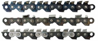
The handle of the device is made of materials with low thermal conductivity. This is necessary to ensure that heat from your hands does not affect the measurement results. Rods are working elements that are fixed to the tip depending on the distance between the walls of the part being measured.
This is interesting! Rods are usually supplied with the device, which expands its measuring capabilities. They are made from hard steel grades, which is necessary to prevent the slightest deformation during measurements. This is important to consider if you plan to make the rod yourself. There are no difficulties in this, since you need to select a suitable workpiece from hardened steel and cut a thread in it that matches the tip of the device.
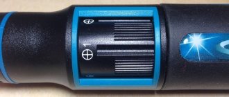
There are two scales on the pointer indicator of the indicator pin. One scale is the main one (its division value is 0.001 mm), and it shows the relative deviation from the original position, and the second one serves to indicate the number of full revolutions of the main hand (one full revolution is equal to 1 mm).
Indicator-type devices are not designed to determine the exact dimensions of internal holes, but to identify the presence of deviations on the internal surface of the part along its entire length. The magnitude of their error ranges from 0.025 to 0.15 mm. Indicator bore gauges are classified into two types - mechanical or pointer and digital or electronic. Electronic devices are characterized by high accuracy and ease of use. Their main drawback is the price, which is 2 times higher than the cost of an analog device.
If it is necessary to obtain high-precision values, the NI-V device is used, which differs from classical models in the design of the measuring head. Its accuracy is 1 micron. Such tools are used specifically to make high-precision measurements of small holes.
This is interesting! The work of the relative bore gauge is to transmit the amount of force or degree of compression of the rod to the indicator pointer.
It is worth noting that there is no specific classification for the design of bore gauges. They are divided into two types - micrometric and indicator. Each type has its own subtypes, which differ in design and type of contact with the surface. They come in lever, cone, wedge, collet, ball, telescopic, with side jaws and others. In this material we will look at how to use a bore gauge (shtihmas) of the indicator and micrometric type, as well as what needs to be done before taking measurements, and what determines the accuracy of the results obtained.
Checking, setting and using indicator and micrometric bore gauges
According to the instructions, the bore gauges must be checked and adjusted before each use. This is necessary to obtain the most accurate measurements, as well as to determine whether the characteristics of the device comply with standard indicators.
Checking micrometric bore gauges
To check the bore gauge, proceed as follows.
- Visually inspect the device, check the markings and make sure there is no noticeable damage.
- Test the bore gauge and make sure that all parts of the tool interact correctly.
- Using an instrumental microscope, measure the width of the streaks on the stem and micrometer drum.
- Check the distance from the end of the drum to the stem.
- Check the radii of curvature of the measuring surfaces on the tip and micrometer head.
- Using a horizontal optimometer, determine the error in the readings of the micrometer head.
- Using an optimometer or horizontal length gauge, determine the total error of the head with attached extensions.
- Determine the runout of the point of contact of the measuring surface of the bore gauge.
- Determine the dimensions of the installation standard at the points of its measuring surface.
Note! Devices with an upper measurement limit of more than 1250 mm require additional testing for rigidity.
How to set up and use a micrometric bore gauge
- The first stage is preparation. Using the setting gauge, adjust the bore gauge to zero. To do this, turn the drum until the zero mark exactly coincides with the longitudinal line of the stem. After this, tighten the locknut.
- After adjusting the bore gauge, extend it to the desired size using the extension(s). Attach several devices in descending order of size.
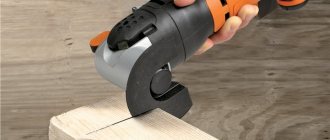
- You can start measuring. Insert the bore gauge into the space to be measured, placing the tip on one of the surfaces. Then rotate the drum until the second tip touches the opposite surface.
Image #1: Using a Micrometer Bore Gauge
Checking indicator bore gauges
To check the indicator bore gauge:
- visually inspect the device, check its integrity, make sure there are no visible damages;
- check the correct interaction of the device parts;
- make sure that the technical and metrological characteristics are normal.
How to Set Up an Indicator Bore Gauge and Use It to Measure Bores and Inspect Cylinders
To start working, the indicator bore gauge must be set to zero. This can be done using a gauge ring or gauge block.
Photo No. 3: using an indicator bore gauge
To measure the characteristics of a hole, a bore gauge is inserted into it perpendicular to the axis. By the direction and magnitude of the deviation of the indicator arrow, one judges how much the measured size differs from the reference one. If the arrow deviates to the right, then the measured size is smaller than the specified one, and if it deviates to the left, then it is larger.
Image No. 2: checking the cylinders using an indicator bore gauge
Working with micrometric bore gauges
In general, it is divided into two types: the first is preparation (adjustment, in order to confirm the accuracy of recording values, and zeroing), the second is direct reading. Let's look at both stages and actions at each of them.
Verification
We will present the general mechanism for its implementation below, in the section on operation. Here we will say that it is carried out only in relation to the model set “to zero”. To do this, at an ambient temperature of 20 0C, perform the following steps:
- place the spherical head of the tool between the jaws of the measure;
- press the required surfaces by rotating the drum;
- fix the assembly using a special screw;
- make sure that the longitudinal line on the stem is located exactly along.
Then they move on to taking readings.
We offer you to see how to set up a micrometric bore gauge; the video will answer those questions that arose during the reading process, and which would be too long to talk about in text format.
All actions should be performed in accordance with GOST 17215-71; According to this method, the interval between verifications is 1 year. The conditions for their implementation must always be the following:
- humidity level – no more than 80%;
- room temperature – from +15 to +25 degrees Celsius.
Attention, the device must be set to zero before each new reading. In order not to provoke distortion of the values, it is worth holding the instrument while adjusting by the bushing, which will not heat up from the heat of the hand, unlike the steel rod.
How to measure correctly with a micrometer-type bore gauge
The following steps should be followed:
- set the approximate diameter of the required hole on the device;
- position the spherical head inside this cavity so that it is located at an angle of 90 degrees with respect to the longitudinal axis;
- press the tool against both walls at once using a drum and a rotating ratchet;
- tighten the locking screw to secure the result and remove the rod with the tip;
- take the resulting value and add to it the length of the head along with the extension (if one was used).
Agree, there is nothing complicated and the result is quite accurate (even taking into account the error, which is insignificant). See how a micrometric bore gauge works and how to use it: the video will help reinforce the impression and clearly show some specific points. For example, it will explain better than words how to rock the device in cylindrical holes. Agree, it is quite difficult to talk about the specifics of movement in the longitudinal and at the same time transverse directions, and yet this operation must be carried out to determine the minimum and maximum values.
So the video in this case will be doubly useful - it will clear away doubts and at the same time show how, in practice, add three values to get the final one.
Please note that the operating conditions are the same, that is, +15...25 0C with a humidity of no more than 80%.
Helpful tips for using and storing micrometric and bore indicator gauges
- Remember to check and adjust the bore gauges before taking measurements.
- Do not remove the adjustment screws to maintain their dimensions.
- When extending micrometer bore gauges, do not overtighten the connections.
- When taking measurements, support the bore gauges in places with minimal deflection.
- Do everything as carefully as possible. Avoid falls and impacts.
- Clean scales regularly to remove dirt.
- Store bore gauges in special cases in rooms and areas with low air humidity.
Checking bore gauges
Like all indicator instruments used in production, bore gauges must undergo periodic verification. They are carried out in laboratories certified by Rosstandart. After verification, markings are applied to the products, carrying information about the suitability/unsuitability of the instruments for carrying out measurements with the declared accuracy.
Bore gauges must be verified in accordance with the metrological testing plan approved by the enterprise, but no less than once every three years. Based on the results of inspections, protocols and acts are drawn up. Unsuitable instruments are excluded from use.