Milling is the cutting process of metals and non-metallic materials, in which the cutting tool - the milling cutter - has a rotational movement, and the workpiece being processed has a translational movement.
It is used for processing planes, curved surfaces of parts, threaded surfaces, teeth of gear and worm wheels, etc.
It is carried out on milling machines.
This definition is given by the Polytechnic Dictionary (Moscow, Soviet Encyclopedia, 1989). It clearly requires addition, because the possibility of milling with hand-held power tools is not mentioned at all. This is what our article is dedicated to.
Let's start with the fact that there are different types of manual milling cutters: edge cutters, rod cutters, rodless cutters, and simply specialized ones, for example, for cutting in door locks or repairing window frames. Let us dwell in detail on the most universal and, as a result, the most popular - rod ones.
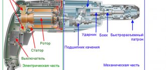
Such a tool consists of two parts: the upper part, which includes the motor, handles, collet clamp, vertical position clamps, and the lower part - with rods, support sole and turret stop. Machines of this type are distinguished by the fact that they allow immersion into the material being processed to the required (within the limits of capabilities) depth.
Using examples of specific operations, we will consider important design features of modern devices of this type.
Getting ready for work
Let's start with the basics - preparing for work. Depending on the material and task, a cutter is selected. For soft wood, plywood, MDF and aluminum, an attachment with high-speed steel (HSS) knives is used; the more expensive, precise and resistant one with carbide blades (HM) is not prohibited.
In other cases - chipboard, hardwood, composite compositions such as artificial marble and the like - the use of NM is mandatory. As mentioned, one of the important features of carbide blades is precision: they leave a cleaner surface.
Depending on the diameter of the cutter and the material, the rotation speed is set. Since the adjustment wheel is usually marked in conventional units, you will have to use instructions that indicate when to set what. Generally speaking, setting the speed is a very responsible procedure.
Firstly, large-diameter equipment may not withstand too high a speed, and secondly, it is important to choose the right mode. If the frequency is too high, there is a risk of “burning” the workpiece; if the frequency is too low, productivity drops and the quality of processing deteriorates.
Having decided on the speed and type of cutter, install the equipment. The risks on the shank will help you do this correctly - you need to focus on them. If you need to deviate from the prescription (or it simply wasn’t there), use a simple rule - fix 2/3-3/4 of the total length of the shank.
When buying “consumables”, it is important to remember that the clamp diameters are different. Typically, collets are available for 6, 8 or 12 mm shanks. If you can’t find the right size equipment, don’t worry – just change the collet. It is an insert located inside the hollow drive shaft and secured with a nut.
So, it's time to clamp the cutter. This is done with an open-end wrench, having previously secured the shaft. Simpler models will need a second key, mid-level tools have a locking button, but the most convenient latch is also equipped with a “ratchet” - in this case you won’t even have to grab it.
The cutter is clamped into the collet using an open-end wrench and a shaft locking mechanism. If the latter is not provided, you will need a second key. In this case, the installation is extremely simplified - the stopper is equipped with a switchable (unscrewing/wrapping) “ratchet”. The cutter is clamped, guided by the markings on it or based on the general rule (2/3-3/4 of the length of the shank).
The “head” of the tool is lowered until the cutter stops against the surface, after which it is convenient to fix it. Next, based on the reach of the cutting equipment and the desired depth of processing, select the lowest of the suitable “legs” of the turret stop. This allows you to pass workpieces in several stages without repeating precise adjustments.
Often the position of each “leg” can be adjusted within small limits. The support rod is lowered onto the selected “stand”, having first released its clamp. Without fixing it, but only pressing it with a finger, they move the movable pointer along it, ensuring that it coincides with the zero of the measuring ruler.
The bar is raised until the pointer coincides with the required division of the measuring scale and clamped with a clamp.
If the operation requires precision, a good router allows you to adjust the set depth value. It is changed without loosening (so as not to knock down) the fixation of the support rod, but by rotating the adjustment wheel. This can be done in advance, having achieved an exact match between the marks of the pointer and the scale, or after a trial pass.
When the “head” is lowered, the cutter will enter the workpiece to the depth set on the calibrated scale.
Preparing the tool for work
The most important thing to do before starting milling is to configure the unit for a specific type of work, taking into account the properties of the material being processed and the type of equipment.
Speed selection
A milling cutter is a unit capable of developing very high spindle speeds, from 8,000 to 24,000 rpm or more. The higher the rotation speed of the equipment, the cleaner the processed surface will be. But you should know that exceeding the permissible speed for certain cutters can cause the workpiece to burn in the processing areas. Therefore, in addition to the rotation speed of the tool shank, the linear speed of the blade should also be taken into account. As a rule, the larger the diameter of the equipment, the higher the linear speed of the cutting edge of the equipment rotates. If you intend to use large-diameter equipment, then the spindle speed will need to be reduced slightly.
Below is a table, using which you can select the optimal rotation speed of the tool depending on its diameter.
In addition, when choosing the rotation speed of the tool, the hardness of the material being processed should also be taken into account. Milling hardwood requires slower speeds than those recommended for a given tool diameter.
You should also reduce the speed of the tool if cutting PVC, processing plexiglass and plastics is required. At high speeds, the plastic will begin to melt and stick to the blades of the equipment. In each specific case, the rotation speed is selected experimentally.
Installation of cutter
Before replacing the tool, you must disconnect the router from the power supply. Disabling the start button will not be enough. It is very important to unplug the cord from the outlet to prevent accidental starting of the engine.
The equipment changes as follows.
- Place the unit on its side so that the spindle locking button is on top.
- Press the button and turn the spindle until it engages the lock. After this, put the wrench on the collet nut and unscrew it. On some models of routers this button may not be available. In this case, you will need 2 wrenches. The first key is put on the nut located on the spindle and acts as a lock (if it rests against the guide rod), and the second key is used to unscrew the collet nut.
- After loosening the collet clamp, remove the cutter shank from it.
- Next, insert the new equipment, immersing its shank into the collet to a depth of at least 20 mm, that is, until it stops.
- Tighten the collet nut. The tool should be tightened with sufficient force, but not so much as to strip the threads.
- Remove the lock from the spindle.
It should be remembered: the nut of the collet clamp cannot be tightened if there is no equipment in it. This will cause it to break.
Setting the processing depth
Almost all milling units are equipped with depth regulators. Setting the tool immersion depth is as follows:
- Place the unit on a flat surface, for example, on a table.
- Place the smallest step on the turret stop (1) under the plunge stop (2).
- Remove the lock from the depth stop by slightly unscrewing the screw (3) so that the stop (2) can move freely.
- Unlock the unit's immersion mechanism. In some milling cutter models, the motor is fixed to vertical rods using a single rotating handle. There are also a considerable number of models of these units, where the drive is fixed using a special rotary lever.
- Lower the motor until the cutter touches the workpiece. This should be done slowly to avoid the blades hitting the part.
- Next, you should fix the engine on the guides again.
- Lower the depth stop (2) to the lowest step of the turret (1).
- Set the slider (4) to “0” on the scale (6).
- Raise the limiter (2) to such a height that opposite its slider (4) on the scale (6) is the value of the dive that you want to perform. For rough adjustments, the limiter (2) is raised or lowered by hand. More precise adjustment of the tool's immersion depth is made using the fine-tuning mechanism (5).
- The position of the limiter (2) should be secured with the locking screw (3). Now you can unlock the immersion mechanism and lift the equipment along with the motor up.
As a result, if you lower the drive until the stop (2) touches the lowest step of the turret stop, you will get maximum extension of the cutter relative to the base of the unit. This amount of immersion of the tool into the workpiece will be final, that is, it will have the required depth.
If you need to make a deep groove that cannot be selected in one pass, then you can use a turret stop to gradually immerse the tool into the workpiece . To do this, place the highest step of the turret stop (1) under the depth stop (2) and carry out milling. Next, place the next, lower stop under the stop, and again make one pass with the tool. When the stop reaches the lowest stop, the required groove depth will be obtained. The following figure shows how the tool is gradually deepened into the workpiece when using a turret-type stop.
Milling depth
The next setup step is setting the immersion depth. It is set by a vertical stop, which can have several stages of adjustment. The most popular is the position of the stop itself. Having rested it on the lowest of the legs of the “revolver” (if possible), loosen the clamps of the stop (usually a wing clamp is implemented) and the “head” itself and lower it until the cutter touches the surface.
Note that it is not at all necessary to use a workpiece; it is better to perform this operation on the plane of the workbench, without the risk of damaging the part.
Now you need to fix the movable stop or simply hold it with one hand, and with the other set the movable pointer (it “moves” up and down) opposite the zero division of the measuring scale, thereby calibrating the ruler. That's it, she's ready to go.
By moving the stop and following the pointer, adjust the depth and tighten the screw of the movable stop. If the router is “simple”, then the adjustment is complete. Otherwise, the immersion depth is adjusted more accurately. The position of the movable (already fixed) stop is changed with an accuracy of tenths of a millimeter by turning the adjusting wheel.
It has latches (“clicks” along the divisions) or simply rotates tightly. The first option is better, since the installation will not fail during operation. It is good when such adjustment is implemented within wide limits, and it is very convenient when it can be done directly during operation.
Milling
Without going into the specifics of the operations and skipping the “Positioning the machine on a plane” point, we’ll tell you how to get started. Having established the maximum immersion depth, it is, if necessary, “divided” into several steps - the turret stop is designed for this. In the vast majority of cases, it has three adjustable legs.
Sometimes there are more of them, for example eight, which, however, is not considered a sign of a high-class instrument, but rather speaks of originality. Without touching the leg on which the immersion depth was set, set the steps higher. The logic of action here is the same as in the case of revolutions - too large a cross-section of the passage at once will lead to slow movement and “burning” of the material, too small - to a loss of productivity.
Optimum is important. By turning the drum and moving from a high stop to a low one, they move along the workpiece to the desired depth.
Starting each pass, proceed like this. Turn on the motor, lower the cutter (into the material or outside the workpiece, depending on the situation) and secure the “head” with a stopper. If there are several passes or there is no confidence that the operation was successful, it is repeated. It is important to remember that you need to move along the workpiece in a strictly defined direction - the material is towards the rotating knives.
It is impossible to drive the router “backwards”, as this will lead to defects. The direction of movement is usually indicated by an arrow on the sole; it is the same for all models.
A few words about the rod mechanism for raising/lowering the “head”. It is important to pay attention to the manufacturing class. Movement should be smooth and easy, without distortions or backlashes. It’s good when the stopper acts on two rods - with this arrangement, the rigidity and accuracy of fixation is higher.
We hope that the reader has already understood that the main thing in a router is adjustments. They are required to ensure accuracy (this, by the way, largely depends on the rigidity of the structural elements) and convenience. But if you delve into the intricacies of performing operations, it becomes clear that something else is no less important - the system.
By it we mean a manual machine with devices for positioning it on a plane (without the latter, the router will be of little use, at least its versatility will suffer greatly). Let's start the story about the “mill + guide vane” system with the simplest cases.
Working with a hand router
Types of work performed by a milling cutter Milling cutters Fastening the cutter in the router spindle Setting the milling depth Selecting the rotation speed mode of the cutter Direction of rotation of the cutter Milling Basic safety measures when working with a router Separate articles: Devices for a manual router Homemade milling table
There are different types of hand-held milling cutters, but the most used and versatile is the hand-held plunge cutter, the operation of which is described below. Plastic, aesthetically perfect wood and a universal hand router. This combination allows you to obtain products of almost any shape - from the simplest in the form of straight planes, to the most complex, more suitable for works of art than for utilitarian things. Working with a manual wood milling machine provides an opportunity to fully enjoy creativity, creating original, exclusive products.
Working with a hand router
Types of work performed by a milling cutter
All operations that are carried out using a manual milling cutter can be divided into several categories.
Milling of grooves, grooves, quarters
and other recesses in the workpiece, which can be located both along and across the layers, be open (proceed to the edge) or closed. With some exceptions, these forms perform certain structural functions - most often they form detachable and permanent connections.
Grooves, grooves, quarter
Edge milling
— profiling. It is used for the production of molded profile products (cornices, skirting boards, platbands, glazing beads, etc.), as well as for interior design, furniture manufacturing and various kinds of crafts. These elements, in addition to being functional, also carry a decorative load.
Finished edges
Milling complex surfaces and contours
when creating original furniture, exclusive interiors and manufacturing products for various purposes that claim artistic sophistication. At the same time, templates are widely used to copy repeating complex shapes with great accuracy, making them almost completely identical.
Curved contours
Milling of special elements
, carrying a purely functional load. These are grooves and holes for awnings and locks, tenons, etc. In mass production, these elements are made using specialized milling cutters (filler cutters, etc.). But in everyday life, universal hand-held milling cutters can handle them quite successfully.
Recess for hinge
Milling cutters
A hand router processes wood using special cutters consisting of a cylindrical shank (collets for shanks with a diameter of 6, 8 or 12 mm are more common) and a working part with a cutting edge. There are a huge number of cutters that differ in size and design, cutting edge shape, and material. For soft wood, cutters with knives made of tool high-speed steel are used, for hard materials (oak, ash, beech, aluminum, etc.) - from hard alloys.
Milling cutters
To give a product a certain shape, it is necessary to ensure precise positioning of the cutter relative to the workpiece in three coordinates. The vertical position of the tool is ensured by the immersion mechanism, which moves the motor with the cutter along the vertical guides of the frame and locks it in the desired height position.
Positioning in the horizontal plane can be achieved in various ways. Using a guide bearing mounted on the router, or a guide bushing attached to the bearing surface of the router, as well as many special devices supplied with routers and purchased independently or made by hand. There are a large number of manuals and recommendations describing how to work with a router using these devices, read one of them here.
When using cutters with a guide bearing, the latter rolls along the edge of the workpiece or template located below or above the workpiece, thus providing a certain distance between the cutter and the part. Milling cutters that have a guide bearing and process the edges of parts are called edge cutters. They are used only for processing the edges of workpieces. There are different shapes of edge cutters.
Some types of edge cutters
Profile cutters
(a and b) give the edge various shaped profiles that carry a decorative load.
Cone cutter
(c) designed for bevelling edges at an angle of 45°.
Moulder cutter
(d) used to round edges. It forms a quarter-circle profile and comes in different sizes with a circle radius of 3-16 mm.
Disc cutter
(e) cuts a horizontal groove of varying depth and width in the workpiece.
Seam cutter
(f) is used for milling quarters that perform a wide variety of functions.
Fillet cutter
(g) used to obtain fillets on the edge. It is used to make edges decorative.
Milling cutters without guide bearings, called slotted cutters, are designed to cut the workpiece anywhere. Their use requires the use of devices (read about branded and homemade devices for a manual router here) that ensure positioning of the cutter in the horizontal plane.
Some types of slot cutters
Rectangular slot cutter
(a) is perhaps the most used. It is used for milling grooves that ensure the connection of parts - both one-piece and detachable.
Fillet cutter
(b) creates semicircular grooves or grooves in the workpiece, often performing decorative functions.
V-shaped cutter
(c) forms a groove with walls located at an angle of 45°. If you insert the cutter to a greater depth, you will get a groove with vertical edges. Using a V-shaped cutter, letters and various decorations are cut out.
Dovetail cutter
(d) is usually used in furniture production when making open and hidden tenon joints.
Fastening the cutter in the router collet
The cutter can be installed both in the engine removed from the frame and in it. It is carried out in the following sequence:
- The router is laid on its side.
- The spindle is secured against rotation - depending on the design of the router, with a wrench or a locking button.
- The clamping nut of the collet is released (if it is screwed onto the collet) or screwed on.
- The cutter shank is inserted into the collet until it stops or at least 20 mm.
- Using a wrench (if the spindle is fixed with a wrench, a second wrench is required), the clamping nut is tightened and the spindle is unlocked.
If there is no cutter in the collet, the clamping nut should not be tightened. This may damage the collet.
Setting the milling depth
Working with a milling cutter involves performing various adjustment operations. One of the main ones is setting the milling depth. It may differ slightly for milling cutters of different models, but its principle remains the same for all plunge routers. The essence of the setting is that when the cutter reaches the required depth, the plunge limiter rests on the turret step stop and prevents further immersion of the cutter.
Setting the milling depth: 1 — turret stop, 2 — immersion depth limiter, 3 — depth limiter locking screw, 4 — limiter slider, 5 — fine-tuning mechanism, 6 — immersion scale, 7 — spindle lock for installing the cutter.
The operation is performed in the following order:
- The milling cutter is installed with its supporting surface on the workpiece.
- The turret stop, which sets the immersion depth, is installed with its lowest stop opposite the end of the stop.
- The limiter locking screw is released, as a result of which the latter gains the ability to move freely in its guides.
- The mechanism of immersion (lowering) of the router is unlocked.
- The motor slowly lowers down until the cutter touches the part.
- The engine lowering mechanism is blocked again.
- The depth stop is lowered until it touches the lowest stop.
- The limiter slider is set to “0” on the dive scale.
- The limiter rises to the position at which its slider shows on the immersion scale the value of the milling depth that needs to be set. This operation can be carried out by raising and lowering the stopper by hand (coarse setting) or using a fine adjustment mechanism (fine setting).
- The limiter locking screw is clamped, fixing the slider in the installed position.
- The immersion mechanism is unlocked, and the cutter and the motor rise upward.
Now, if you lower the motor with the cutter to the lowest position (until the end of the limiter touches the shortest pin of the turret stop), the cutter will penetrate into the workpiece to the depth the value of which is set on the scale.
If milling is carried out to a great depth, it must be carried out in stages. This is done by turning the turret stop so that during the first passes the depth stop first rests against the higher stops, and only in the final pass against the lowest stop.
Step-by-step groove milling
Selecting the cutter rotation speed mode
Unlike rotary hammers, screwdrivers and drills, the rotation speed of the cutter is relatively high - usually over 10,000 rpm.
This is explained by the fact that the faster the cutter rotates, the cleaner the cut surface is. However, too high speeds are also undesirable, since the surface being processed can become charred, and excessively increasing centrifugal forces - especially when using large-diameter cutters - can lead to breakdowns. Therefore, the rotation speed of the cutter is adjusted within certain limits depending on the material being processed and the diameter of the cutter. In fact, the cleanliness of the machined surface is determined not by the rotation speed of the cutter, but by the linear speed of movement of the cutting edge relative to the material. The larger the cutter diameter, the higher the linear speed. Therefore, when using large-diameter cutters, the rotation speed is set lower. For example, for a cutter with a diameter of 10 mm, the speed should be from 20,000 rpm and above, for a cutter with a diameter of 40 mm - 10,000-12,000 rpm. Specific values are specified in the operating instructions. The rotation speed is also determined by the hardness of the material being processed. The higher the hardness, the lower the number of revolutions of the cutter should be.
After prolonged operation at low speeds, the milling cutter should be turned on for several minutes at maximum idle speed to cool the engine.
Cutter rotation direction
The direction of rotation of the cutter can be along or counter. In the first case, the cutting edge of the cutter moves relative to the material in the direction opposite to the movement of the router (the edge cuts into the rough surface of the board and comes out at the bottom of the groove being milled). During counter milling, the edge of the cutter moves in the same direction as the movement of the router (plunging begins at the depth of the groove). Up-milling is correct; down-milling is used only in exceptional cases - when processing edges in which the arrangement of fibers leads to flakes. This method is considered unsafe, as it can lead to the router being pulled out of your hands.
Correct direction of cutter rotation
Milling
Milling parts with a manual router, as a rule, involves the use of various devices to ensure the exact position of the router.
Therefore, milling techniques are discussed in the article Milling Devices, which describes not only proprietary devices, but also those made by hand. Before starting milling, the following must be done:
- The cutter is fixed in the collet.
- The engine speed suitable for the job is set.
- The required milling depth is set using the plunge limiter (when working with plunge cutters) or a certain value of the cutter overhang in relation to the base is fixed (when working with edge cutters).
- A guide bearing or ring (when working with edge cutters) or other device is installed to ensure the required path of the cutter. In this case, the optimal cut thickness must be set - as a rule, no more than 3 mm.
The methods of working with a manual milling cutter differ somewhat depending on the mode in which the work is carried out. But in any case, the router is installed on a base - the workpiece or an auxiliary surface. The guide element of the router (bearing, ring, edge of the sole or other surface) is pressed against the guide edge (part, rack or template), after which the engine is turned on and the cutter first begins to immerse (if the submersible mode is used), then the router moves smoothly along the trajectory , specified by the guide element.
Basic safety precautions when working with a router
Safety precautions are described in detail in the operating instructions for the router. The most important ones that are simply vital to know include the following:
- Attaching the cutter and setting the router must be done with the power cord unplugged from the outlet.
- Working with a hand router requires care and concentration. When milling, you must stand firmly on your feet and hold the router firmly in your hands. You cannot work while tired, distracted or drunk. This could result in the router being pulled out of your hands and causing serious injury.
- The workpiece must be firmly fixed, otherwise it may be torn out of place by the cutter and thrown with great force and speed.
- When the cutter comes into contact with the material, you need to be especially careful to avoid the so-called kickback - an effect when the cutter hits the material and receives a reciprocal reactive blow, which can lead to the cutter being torn out of your hands, breaking it or causing injury. To prevent a kickback from occurring, you need to hold the router firmly in your hands, firmly press it to the base and smoothly move the tool. The thickness of the cut layer should not be too large - no more than 3 mm.
- Clothes should not have loose elements that could get wrapped around the cutter.
- Avoid inhaling fine dust generated during milling. It is harmful to the lungs. Dust can be sucked out with a vacuum cleaner or a respirator can be used.
When using the content of this site, you need to put active links to this site, visible to users and search robots.
Literature
Cutter with support bearing
The most elementary and compact device that sets the position of the machine is the cutter itself, if it is supplemented with a miniature ball bearing. It is located under or above the cutting knives and, accordingly, rests on the upper or lower edge of the edge. With the help of such equipment, shaped edges are obtained or grooves are cut for a connection, edging, seal, etc.
The advantages of the method include the ease of preparatory operations (you only need to adjust the vertical position) and the ability to accurately process rounded and curved edges (a typical example is a tabletop). The disadvantages follow from the advantages - it will not be possible to make a curve straight.
Application of an electric milling machine
Working with a manual wood router helps to carry out the following carpentry operations:
- Processing of flat and shaped surfaces, edge profiling of platbands, skirting boards, cornices, glazing beads.
- Formation of technological and shaped recesses (grooves, ridges, etc.).
- Making through and blind holes.
- Cutting complex parts from wood and copying them.
- Applying inscriptions, drawings, patterns on the surface (engraving).
- Inserting locks and hinges on doors.
- Making a tenon joint. This is a complex process requiring special skills, which results in a highly durable assembly of wooden products.
Depending on the type of work performed with a manual wood router, video lessons of which can be viewed at the end of the article, you will need the following equipment:
- Milling cutter
- Jigsaw
- Chipboard
- Electric drill and drill bits
- Templates
- File
- Protective clothing and respirator.
With the help of such a tool, a novice craftsman can bring old furniture back to life and carry out small carpentry and decorative work with wood around the house.
Rip fence
All of the above can be done with a regular cutter without a support bearing (it’s cheaper) if you use a copy ring or a rip fence. Let's start with emphasis. All milling cutters without exception are equipped with it, but this does not mean that it is the same for everyone. In the simplest case, the stop is a bent metal plate on two steel rods with a cutout in the center.
Guides with locks are provided for them in the sole of the router. To ensure rigidity, they are made long (the entire slab) or short, but double - two spaced apart for each rod. Fixation occurs at a minimum of two points (one on each side), and a maximum of four.
In the “primitive” version, such a stop has significant disadvantages - low rigidity of the stamped structure, difficulty in fine-tuning the position, restrictions on the diameter of the cutter used (it must fit in the central cutout), and the inability to adjust the base of the supporting surface. As the accessory becomes more complex, it gets rid of these shortcomings. As an example, let's look at the most interesting construction, omitting the intermediate ones.
The rods are fixed in the sole not with separate clamps, but with one, acting on both sides at once - this is more convenient. After the “pins” are clamped, the position of the support shoe is set - it is not made integral with the rods, but is capable of moving along them. It also has two clamps with one (which is more convenient) or two locking screws.
After rough adjustment, loosen the additional lock and move the supporting part of the shoe, rotating the adjustment wheel. As with the vertical adjustment, there are dimensional divisions here. Having set the required value, the additional stopper is fixed.
Next, if necessary, the pads are moved apart or brought closer together, thereby expanding the base and/or adjusting the size of the central gap between them to fit a cutter of a specific diameter. The final and most important note is that the base of the mechanism is not stamped steel, but cast from a light alloy.
The rip fence is useful when working with an edge or when milling into a surface at a given distance from the edge. They work both along an even contour and along a curved one. The “disadvantages” of such a positioning device are as follows: limited distance from the edge and the complexity of the process.
High-quality milling requires a certain skill and a steady hand. For example, it is easy to “overwhelm” the line at the beginning and end of the workpiece when the stop does not contact the edge along the entire length of the base. If the indentation is large, the risk of deviating from the perpendicular to the edge (or tangent to it when it is curved) also increases.
For convenience and accuracy of work, the base of the side support is adjusted. When the jaws are as close as possible, it is easier to start and finish the passage. When bringing the “shoes” closer together, you must remember that when lowering the cutter, it can meet them if the distance from the edge is insignificant.
A maximally expanded base will facilitate long passes at a great distance from the edge, when the torque is high, moving the stop line away from the perpendicular to the edge.
The router is placed on the marking line, the stop is brought to the edge and fixed. In this case, both rods are clamped by rotating one handle, usually with several “personal” screws.
Having released the lock of the precision adjustment mechanism, rotate the adjustment screw to achieve precise installation of the stop.
After the adjustment is completed, the mechanism is fixed.
Fine adjustment allows you to achieve complete coincidence of the marking line and the axis of the cutter. To facilitate the procedure, a “sight sight” is made on the sole, which is easier to navigate.
Useful devices
There are a lot of devices that make working with a router easier and allow you to perform complex operations.
Most of them are designed to perform specialized types of woodworking, but there are also simpler ones that are useful for the home craftsman.
One such device is a table. The router is attached from below, the cutting organ passes through the hole and looks out. Working with such a table is reminiscent of processing parts on a stationary machine. You can install a stop, a clamp, or use a template. The advantage of this method is safety and the possibility of reliable control of the workpiece.
For copying on a scale, a pantograph or copying conductor is used. It can have a rather complex design in the form of a coordinate machine, or consist of several strips. A probe is attached to one end and is guided along a template. A milling cutter is attached to the other end, repeating all the movements of the probe and copying the reference part on its own workpiece.
There are also simpler types of devices, for example, a guide rail. It is a straight, even bar with a groove into which the ridge of the parallel stop is inserted. The tire itself is attached using clamps or double-sided tape. Useful when working with large-area parts, many grooves or other elements.
Devices for working with a manual wood router can be made independently or purchased ready-made. Factory templates are usually made of metal, durable and accurate. However, the prices for such products are quite high, which forces home craftsmen to make the necessary devices with their own hands.
Important! You should start making any additional devices after you have acquired some skill in working with a hand router and have an understanding of the meaning and necessity of having auxiliary devices.
In the video tutorial, the master teaches and shows what interesting things can be done with a hand router:
Guide rail
When it comes to straight lines, a guide rail is a good alternative to the rip fence. It is fixed at an arbitrary distance from the edge and at any angle to it. Instead of a stop, a special shoe is installed on the rods - it slides along the tire and sets the position of the router. Due to the support on the guide, a height difference may occur as the machine is raised above the workpiece. To avoid holding it suspended, extend the support leg (if provided).
In a special configuration, such guides also serve for precise milling of holes, which is especially important when making furniture (the ruler has holes with a standard pitch, the machine has a stopper; all you have to do is select the desired positions and drill).
Important note: a set of parts for working along the guide is not purchased in all cases; it must be included in the manufacturer's list of accessories and be suitable for the specific router.
The tire is fixed relative to the workpiece. The router is positioned along it using a “shoe” similar to a side stop, and can be placed at different distances from it. Since only part of the platform rests on the tire, an additional “leg” is extended.
Copy ring
In some cases, the copy sleeve is installed in one movement; in this case, alignment is not required.
There are other additional devices, but more on them later. Now let's talk about the copy ring - one of the mandatory attributes of a manual router, almost always included in the package. The device is very simple, but easy to use and useful.
Typically, this is a stamped steel plate with a raised ring around the center hole, which serves as a stop that tracks the copy template. The sleeve is selected for a specific cutter. Ideally, it should pass through the central hole with a small gap. In other words, you should not rely on the only ring that comes with the tool.
Most often, the bushing needs to be centered using a special cone. It is inserted into the collet (all the way to the copy ring), thereby leveling the position, and only then the mounting screws are finally tightened. Sometimes quick-release clamps are used instead of the latter, then there is no need to center anything.
The principle of operation of the equipment is simple - the protruding ring side in the center is guided along the template. In this case, the cutter follows the bends on the workpiece. The main “disadvantage” of such a “device” is one - it is impossible to get an exact copy - it will always be larger than the original.
This method is convenient in mass production (naturally, we are talking about household scales) or when the workpiece is valuable enough and it is worth making a template for its processing.
For precise and comfortable work, the router must have a smooth sole. When the copy sleeve is not in use, the groove intended for it is closed with a ring.
For precise and comfortable work, the router must have a smooth sole. When the copy sleeve is not in use, the groove intended for it is closed with a ring.
A similar bushing with the required diameter of the support ring is screwed on, but the mounting screws are not tightened.
For precise positioning of the bushing, a centering body is installed. It is clamped into a collet like a regular cutter (with the only difference being that the support sole is pressed against the body).
After installing the cone, the lowering mechanism stopper is released, and the sole, under the action of lifting springs, presses the cone to the bushing, thereby accurately centering it. Having secured the stopper again, the bushing fastening screws are securely tightened.
It is recommended to select a ring with the smallest possible diameter of the central hole, not forgetting that the working part of the cutter should pass through it freely.
If the template provides reliable support for only one side of the platform, an additional “support” is pulled out on the other and secured with a locking screw. If you don't do this, there is a high risk of losing exactly.
Basic rules of use
In this chapter we will try to answer the question: “How to work with a hand router correctly?”
A high-quality result is possible only if certain rules and working conditions are observed. These include the following wood carving requirements:
- It is necessary to work only with a sharp tool. If the treated surface is burnt, fleecy or has many small chips, the cutter should be replaced;
- The workpiece must be securely secured using clamps or other devices. You cannot hold the workpiece in your hands;
- The feed of the router should be smooth and leisurely, without jerking. Do not try to immediately remove a thick layer of material. In some cases, the excess mass is pre-drilled in order to remove a small remainder with a milling cutter;
- The cutting tool is changed only when completely disconnected from the network.
Example of table top milling:
Compliance with these requirements should become a prerequisite for work for a home master.
The cleanliness of the cut is ensured not only by the degree of sharpness, but also by the cutting speed. The higher the number of revolutions, the cleaner the processed surface. For hard materials - aluminum, dense wood, etc. — the shaft rotation speed should be reduced slightly so as not to overheat the cutting edges of the cutter.
When milling edges, the feed is made so that when moving away from you, the part remains to the left, and vice versa. If you need to make a groove, the direction of movement does not matter.
Let's look at common techniques for working with a hand router.
How to cut a circle
In order to cut a circle with your own hands using a router, you need to use special templates or devices.
First of all, it is necessary to clarify what exactly is meant - you need a part in the form of a circle, or a hole.
The delivery set includes a parallel stop.
If you drill a hole in it, you can make a simple circular jig. You need to turn the stop upside down, screw it in the center of the future circle onto a screw, use clamps to set the desired diameter of the hole and cut it in a circle. Sometimes the kit comes with a compass rod, which makes it even easier to make round holes.
When a circle is needed, a template should be used. It is a sheet with a hole of the required diameter. It can be made from plywood or fiberboard, which is recommended to be glued in half. This will result in a stiffer and thicker sheet, from which a high-quality template will come out.
The diameter of the template depends on how the emphasis will be made. If you rely on the base itself, then the diameter of the template should be increased by the amount of the platform radius plus the radius of the cutter. In cases where the emphasis is on the copy ring included in the delivery set, the diameter of the template is equal to the sum of the radii of the cutter and the outer convex part of the ring.
As a template, you can also use a ready-made circle into which the copy cutter bearing rests. The easiest way to fix it is with double-sided tape, after cutting off the excess material with an allowance of 2-3 mm.
The quality of work depends on the accuracy of the template. Usually it is cut out with a jigsaw, trying to maintain the shape as accurately as possible. In some cases, a round hole is cut using a jig with a clamped cutter.
Sampling quarter
Selecting quarters with a manual router can be done in several ways:
- Using a rip fence;
- Using an edge cutter with a smaller diameter bearing;
- With the machine platform resting on a flat bar, fixed at the required distance from the edge.
The first option is used when there is a smooth edge and a large quarter size that requires several passes. The second method is used to obtain the same quarter width, since only the immersion depth of the cutting part of the cutter can be adjusted. The third option allows you to make a large-sized quarter when the outer edge of the workpiece is uneven or unprocessed. Wide quarters have to be done in several passes, each time moving the stop a few millimeters until the desired width of the step is achieved.
How to choose a groove
To make a groove with a router, use:
- Parallel stop;
- A strip fixed at the required distance parallel to the groove line;
- A pair of planks between which the router platform moves.
The first two methods require accuracy and attention, since the milling machine can only be focused in one direction. If the master is distracted, the cutting line may go to the side. The third option allows you not only to avoid such situations, but also to increase the width of the groove. The distance between the slats can be increased slightly so that the width of the groove is equal to the diameter of the cutter plus the size of the gap. In this way, fairly wide recesses are made for various furniture parts, locks, and structural elements.
Edge processing, working with a template
For cutting edges, appropriate cutters equipped with a thrust roller (bearing) are used. It is necessary to pre-align the edge, otherwise the cutter will copy all the irregularities and the edge will look sloppy. In addition to edge cutters, templates are used to form a curved shape or produce a batch of identical parts. For work, a copy cutter with a bearing is used. The cutter is pulled out so that the thrust roller rolls along the template, and the cutting part processes the edge of the part.
Let's take a closer look at these working methods.
The width of the part is less than the length of the cutting part
In such cases it is necessary to use a template. The simplest option is to combine two identical parts into a pack. A bearing rolls along one of them, the other is processed by a cutting edge. If there is only one part, you will have to make a template from sheet material - plywood, MDF, chipboard or the like. It is important to accurately repeat the configuration of the part, to avoid the appearance of potholes or irregularities.
Many craftsmen do not like to resort to this method, since the template is often used only once and then thrown away. However, the quality of work is more important than labor costs. You should not spare time and effort, since it will be difficult or even impossible to eliminate defects after processing the edge.
Angle stop
It is possible to get an exact (one to one) copy of the original by installing an angle stop with a feeler gauge (like many other accessories, it can be purchased separately). In this case, the workpiece is placed not under, but above the template. For precise adjustment of dimensions, adjustment of the position of the probe can be provided.
By the way, if you install a support plate or an adjustable stop for working in a horizontal position instead of a bracket with a feeler gauge, you will get a tool for flush milling of edge overlays.
Compass
A special case of curved cutting is along the radius. A compass ruler, purchased separately, will help you complete it without templates, which means more accurately and with less effort.
The sole of the router is rigidly screwed to the “compass”; The radius is set by moving along the “center” guide. The centering pin is inserted into the hole drilled in the workpiece. There are designs in which the “compass” is a side stop or an additional device mounted on the rods.
The disadvantage of this design is that not every cutter will pass through the hole provided in the substrate.
Examples of using
As for the most famous work for a router - along the edge - there are no comments here, everything is already clear: choose an attachment for the desired style and material, a method of positioning on the plane (a cutter with a support roller, copying according to a template using a bushing or an angular stop, according to the workpiece using a side stop or guide bar) and get down to business. Actions with selecting grooves on a plane (decorative or technological) also do not require explanation.
What else can a milling cutter do?
The next group of typical tasks is the sidebar. Most models can easily cope with preparing seats for overhead or furniture hinges. More advanced ones, with increased vertical travel, will help with the installation of mortise locks.
A wide range of applications for hand routers involves joining parts made of wood and its derivatives. The simplest (do not require complex equipment) are tongue-and-groove joints and bindings. They are used in the manufacture of windows, doors and many other prefabricated joinery products. As a rule, two paired cutters are used (profile and counter-profile). As already mentioned, the tool facilitates precise drilling for dowels.
A rather expensive, but worth its price, device is a tenon cutter. Essentially, it is a complex and precision-made workpiece clamp, complete with a copying template. They work on it with a special copy sleeve. It not only rests on the plane of the template, but also “holds” onto it from the reverse side due to a small side.
Two or four mating parts are fastened at once (from the other edge, each pair is worked separately), while special stops set the required displacement of the workpieces relative to each other. Next, set up the router. Clamp a specially shaped attachment (“dovetail”) and set the milling depth in accordance with the reference table. The density of the connection, that is, the gap in the tenon-socket pair, depends on it.
With precise adjustment, it is not difficult to achieve a “zero” gap - after assembly, the structure will hold tightly without glue or other additional fixation measures. Such compounds are used, for example, in the manufacture of furniture from solid wood of valuable species.
It is easy to get connections for a straight tenon - you will need a different template and nozzle.
As part of our article, we briefly outlined the main technological operations, but in fact there are much more of them. Which is not surprising, since the router is even used for artistic purposes to apply engravings (again, with a special pen cutter).
It is important to understand that this tool, with rare exceptions, is not a self-sufficient thing and requires all kinds of equipment and devices. Without them, he will hardly reveal even a quarter of his capabilities.
It is for this reason that you should treat your purchase as responsibly as possible, paying attention not so much to the device itself, but to the list of branded (some may not be suitable!) accessories for it.
Video description
This video shows the main characteristics when choosing a router:
- A system that allows the cutter to start moving smoothly rather than jerkily can help avoid overloading the device when starting work. It also helps to process parts more accurately and prolongs the life of the cutter.
- An electronic device for automatically adjusting speed during operation is capable of maintaining the desired speed if a harder section of material, for example a knot, appears in the path of the cutter. This mechanism stabilizes the operation of the cutter and improves the quality of processing.
- The temperature control module is a very important design element when choosing a router, as it is responsible for the safety of the device. When the mechanism overheats, it automatically turns off the current supply to the motor. Instead, to reduce the cost of the design, a color indicator can be installed, which will show how overheated the unit is.
- Before choosing a router for working in a confined space, you should check whether it has LED lighting for the area in which the work will take place. This is necessary to use the device in places with limited lighting.
Tool with LED backlight Source prosto-instrumenty.ru
- The power cord is a very important element of the router. Its length should be long enough to make it convenient to work at a distance from the outlet. It is necessary that it does not interfere with work and visibility. A wire braided with reinforced thread will be stronger and more durable.
- A mount for installing a nozzle, which makes it possible to connect a construction vacuum cleaner, will help clean the work surface from dust and debris during work. This will protect the device from unnecessary damage, as well as improve visibility and simplify operation.
There are various attachments for installation on the device, since using a router on wood or other material requires the help of special cutters, because each of them can make a cut of a different shape:
- A straight groove cutter is made in the form of a cylinder and is needed for rectangular grooves.
- The U-shaped bit is used for a rounded groove, which is made using a hand-held device.
- A V-shaped cutter can make a groove at different angles of inclination of its walls. To do this, several such nozzles of different sizes are used.
V-shaped cutter Source cdn.vseinstrumenti.ru
Milling cutters
Working with a stop or guide and using a special cutter, make grooves for installing furniture hinges. For precise longitudinal positioning of holes, you can use a special tire that allows you to rigidly fix the position of the router at standard length intervals.
Some tenon joints are made using one cutter (a counter profile is not needed).
Special cutters required for making binding.
Special cutters required for making binding.
One of the cutters (profile) forms the edge of the part; pair (counter-profile) “pass” the end of the mating workpiece.
One of the cutters (profile) forms the edge of the part; pair (counter-profile) “pass” the end of the mating workpiece. This equipment is easy to use and also allows you to mill curved edges.
This equipment is easy to use and also allows you to mill curved edges.
Tenoning device
Depending on the type of template, a cutter is installed. By adjusting the depth of its immersion, the density of the connection is set. It can be assembled by tension or with glue (it is necessary to provide a gap for it). Using special windows in the template, the longitudinal position of the workpiece stops is set and they are turned with the side corresponding to the template.
Next, mating parts are clamped in pairs on each side of the template. They must be cleanly processed and fit tightly.
A special copy sleeve is installed on the router. To increase the accuracy of vertical positioning, it has a lip on the support ring, which allows you to grip the template plate from both sides.
Guided by the general rule of guiding the tool against the stroke of the cutter, the workpiece is passed from the center to the edge. It is recommended to make a trim first (pass the template along the protrusions without “going into” them) - this will avoid chipping.
Main types of nozzles
Main types
For milling work, end mills with a shank diameter of 6.8 or 12 mm are used.
They are sold individually or in sets that include the most popular types of cutters.
There are sets with 7 mm shanks, but it is difficult to find a collet for them. Depending on the purpose and shape of the cut, there are edge and groove cutters. Edges include:
- Profile;
- Conical;
- Moulded (moulded, quarter-rolled);
- Disk;
- Fillet.
A common feature of edge cutters is the presence of a bearing that acts as a stop. Groove cutters include:
- Rectangular (straight);
- Filling;
- "Dovetail";
- V-shaped.
Groove cutters do not have thrust bearings and allow you to cut both on edges and on faces. There are straight cutters with a bearing at the top, just above the cutting edges. Usually its diameter corresponds to the size of the cutting part, which allows you to cut curved shapes according to a template. Such cutters are called turning cutters. They are not included in standard kits; if necessary, they must be purchased separately. Almost all cutters are available in several standard sizes. To make a recess of the required size, you need to select a cutter of the appropriate diameter or profile.