Why does the device spin in the opposite direction?
However, in some cases, vehicle owners are perplexed as to how the starter can turn in the opposite direction for no reason. In other words, the new starter has not been disassembled before, and the wires are running fine. What's the matter then?
It is clear that not a single car owner will want to disassemble a new starter, much less solder the rotor and change the wiring, as some experts advise doing in very serious cases.
So why does the electric motor spin in the opposite direction? Of course, there is no need to consider the motor design in detail here? It's all about the same magnets that were written about above. They essentially perform the function of a stator. Four or six magnets of different polarities are installed inside the starting device. Three magnets of positive polarity and three magnets of reverse polarity. They are arranged alternately, according to the following scheme: “plus” and “minus”, “plus” and “minus”, “plus” and “minus”.
How to reverse rotation on a car starter
To determine the polarity of the magnets, just touch them to each other. If magnets attract each other, it means they are of the same polarity. If they don’t attract, then you have different polarities.
A modern starter, in fact, is nothing more than an electric motor, the rotation of which depends directly on the magnetic field. He doesn't care which way to turn. The direction of rotation is determined by residual magnetism. Thus, if the poles are incorrect, then a polarity reversal has occurred, as experts like to call this process.
Polar reversal - as you might guess, this is a change of poles.
Disassembling the starter should always be carried out according to a predetermined plan. It is imperative to mark the starter cover by drawing with a felt-tip pen along the starter from top to bottom. This way, when reassembling, it will be clear how to install the cover.
It is noteworthy that scooter starters can be easily set to the desired polarity without even removing the cover. To do this, it will be enough to loosen the two guide bolts of the starting device, and then, holding the anchor with one hand, rotate the cover 180 degrees with the other. This will change the rotation of the magnetic field on the starter.
Design and malfunctions of an electric drill
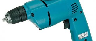
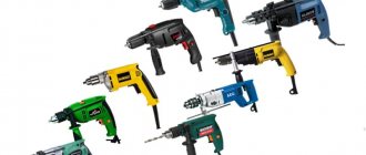
Drills can come in different sizes and colors, but the pattern inside is always the same.
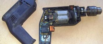
Impact drill device
The main components of an impact drill:
- Cartridge.
- Metal gearbox housing.
- Electric motor.
- Start button.
- Button to switch between normal and shock modes.
- Frame.
- Induction rings.
- Capacitor.
- Network cable.
- Brushes.
- Reverse button.
- Speed regulator.
A simple drill without an impact mechanism does not have a metal gear housing. The shaft and gear bearings are inserted into the drill body.
Hammerless drill gearbox
Basic drill malfunctions:
- Doesn't turn on. Causes: damage to the power cord, wires inside the drill, start button, or start capacitor.
- Engine malfunctions.
- Broken or worn brushes.
- Sparks, smokes, crackles, unpleasant smell. The reason is the brushes or the motor.
- Loss of power occurs due to a faulty armature.
- Damage to the power, reverse, and speed control buttons.
- Bearing wear.
- Poor chuck clamp.
Engine faults:
- Shaft deformation.
- Making an anchor.
- Failure to secure the poles to the frame in the stator.
- Winding wire rupture due to overload or abrasive dust.
- Short circuit to body or between turns.
All of these faults, with the exception of engine faults, are easy to fix yourself. Engine repair is possible if you have certain skills and knowledge. Sometimes it's easier to take it to a workshop or buy and install a new one. Installing any new unit is cheaper than repairing it in a workshop, since professionals charge a fee equal to the cost of the unit for one replacement.
Video: drill device
Recommendations for extending the performance of new and repaired drills:
- The drill should not operate for more than 20–25 minutes continuously after being plugged in.
- Do not overheat the device to the point of burning your hands.
- It is necessary to clean the cartridge from dirt and lubricate it.
- Do not use very dull drills.
This is interesting: Electric hair curlers do not heat up: how to repair it yourself?
Let's move on to reconstruction
Having disassembled the drill, I determined a place to install the button and, using a round file, cut a hole in the body to install the button, soldered wires of the required length to the contacts of the button and began reconnecting the connections. The fact is that the drill has a trigger with a thyristor rotation speed controller, and when upgrading, this must be taken into account.
What is the connection diagram for the drill button?
Of course, it is impossible to state so unequivocally that the buttons on all drills are connected the same way, there are drills with reverse, there are direct connections, so this answer will be more introductory than carrying specific information.
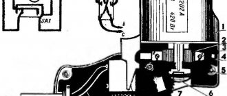
Even on drills of the same type, there is a difference in connecting the button depending on the functionality of the drills; here is an example of connecting an old Soviet drill:
Another connection diagram for a drill with reverse, more or less generally accepted:
On some reverse drills, the following contacts are used on the button:
The top of the button interrupts the pole on the electric motor.
There can be a different number of sockets (wires) for switching the drill button, depending on the functionality of the tool, but at least six - two - network input 220 (phase + zero) - two going to the capacitor and two going to the winding and stator brushes of the electric motor.
If you look closely, you can see short diagrams right on the bodies of some buttons. More precisely and more specifically, you can see the button connection diagram in the manual for the instrument (operation manual)
For example, in many Interskol tool buttons, the power wire sockets are made round, this already excludes the remaining four, two of which go to the stator and two to the capacitor.
The electric drill button is connected according to the following diagram:
There are a total of six contacts on the button into which the wires going to the electric motor winding are secured, the terminal blocks or leads of the start capacitor and the supply of the 220V power wire are clamped.
Here is a visual picture with signed contacts, what to connect where.
The button on the drill is the most painful spare part for those who use the drill in dirty conditions, and especially with dirty hands. No matter how sealed it is, dirt and moisture still get in there, which is why it starts to jam or the contacts burn out altogether. So I had a broken button, after disassembling it, it was decided not to repair it but to replace it. I encountered difficulty finding the original button, so I had to select a similar one and then connect it according to a new circuit. I hope someone will find my knowledge and experience useful.
It should be noted right away that the buttons can be without reverse, with built-in reverse, or with external reverse.
1) A button without reverse, but with a speed controller.
The connection is quite simple, there will be an input and an output, they should be indicated by an arrow, only two wires, one of which is “+” from the network, and the other is output to the winding.
2) Button with built-in reverse.
A characteristic feature of such a button is that all the wiring is located on the body. There will always be two mains inputs, indicated by arrows, but they can be located either close to each other or at a distance.
There should be two more holes for connection along the bottom; they should be connected by a wire passing through the capacitor. It is difficult to mix up the wires to the capacitor, since on the button diagram they should be schematically shown as a break with two vertical segments. from the return of the capacitor the wire will go to the stator winding.
On the top part there is a reverse, namely, three wires will come from it, it is difficult to confuse them, you just need to know the rule - they are connected diagonally between the brush and the stator. Those. two diagonally will go to the stator and brush, and one to the side will only go to the brush, since it goes to the stator from the bottom.
3) Button with remote reverse.
The connection diagram for the reverse button is the same as with a built-in button, but there is one difference: a wire will come from the reverse button itself (in a built-in reverse it goes inside the case).
But in the end, I wanted to warn you that there are many types of buttons and the connection diagrams may be different.
Types of faults in the electrical and mechanical parts of the drill
DIY motion sensor repair
The most common electrical problems are when the drill sparks at the brushes due to significant grinding or wear. A device with heavily worn brushes will not turn on at all. A sign of problems with the engine is the absence of signs of its activation (sound, vibration, etc.). For a drill with variable speed control, reverse and speed control may no longer function.
Mechanical faults - failure of a bearing or gear mechanism, shaft failure. They are manifested by humming, periodic stops of the device, and slow rotation. Sometimes problems arise with the chuck: difficulties in disconnecting the drill, unscrewing the chuck relative to the shaft.
How to determine whether a button is working?
To do this, you will need a regular multimeter (tester) and a screwdriver.
The diagnostic process itself is carried out as follows (using the example of the common drill model DWT SBM-500):
- Remove the drill housing cover by unscrewing several fastening bolts;
- Unscrew the two screws on the power cord clamp;
- We remove the start button block, disconnect the reverse switch (it is usually attached to clips that just need to be slightly bent). The reverse itself is sold separately and can also be replaced if necessary;
- Take a multimeter and set the switch to the beep position. We close the contacts of the tester to make sure that it is working (the device should beep);
- We call the button. To do this, we place one contact of the tester in position 2 (it should be in contact with the wire), and place the second contact on the screw that presses the 220 volt wire. When you press the button all the way, the device should emit a beep. If this does not happen, the button does not work.
How to replace a button?
To do this, you will need a flat-head screwdriver and a regular pin or thin awl.
- The button replacement process itself is carried out in the following sequence (using the example of the DWT SBM-500 drill):
- Unscrew the two screws holding the power cord in place and remove it;
- We insert the awl into the hole in the wire coming from the stator, and remove the wire along with the awl.
- We carry out a similar manipulation to remove the second wire. If you are afraid of mixing up the wires when connecting a new button, we recommend drawing a schematic diagram for connecting the drill power button;
- We take a new button and connect the power cord wires to it in accordance with the drawn diagram. Then we connect the drill itself to the button block. The wires from the stator are simply inserted into the holes until they stop;
- We attach a reverse button to the block;
- We install the block into the seat in the drill body, carefully lay the wires, and press the power cord with two screws;
- We close the cover of the drill housing and conduct a test.
VIDEO INSTRUCTION
Connecting a drill button with a speed controller
Many modern drill models, in addition to reverse, have a motor speed regulator built into the button. This function is very useful because it allows you to set different operating modes for the tool when performing different operations.
As for replacement, the whole process is no different from that described above. It is enough to purchase a new button for a drill with a speed controller and replace it with the old one in accordance with the instructions given.
By the way, if you wish, you can always install a button with speed control on a regular drill - just choose a block that is suitable in shape and size, as well as corresponding to the power of the tool.
How Reverse Works on a Drill
Drill device
Electric motor
. The commutator electric motor of a drill contains three main elements. stator, armature and carbon brushes. The stator is made of electrical steel with high magnetic permeability. It has a cylindrical shape and grooves for laying stator windings. There are two stator windings and they are located opposite each other. The stator is rigidly mounted in the drill body.
The rotor is a shaft onto which an electrical steel core is pressed. Along the entire length of the core, grooves are machined at equal distances for laying armature windings. The windings are wound with a solid wire with taps for attachment to the collector plates. Thus, an anchor is formed, divided into segments. The collector is located on the shaft shank and is rigidly mounted on it. During operation, the rotor rotates inside the stator on bearings located at the beginning and end of the shaft.
Spring-loaded brushes move along the plates during operation. By the way, when repairing a drill, special attention should be paid to them. The brushes are pressed from graphite and have the shape of a parallelepiped with built-in flexible electrodes.
Speed controller
. The drill speed is controlled by a triac regulator located in the power button. It should be noted that there is a simple adjustment scheme and a small number of parts. This regulator is assembled in a button body on a PCB substrate using microfilm technology. The board itself has miniature dimensions, which made it possible to place it in the trigger body. Key moment. This is that in the drill regulator (in the triac) the circuit opens and closes in milliseconds. And the regulator does not change the voltage that comes from the outlet in any way (however, the root mean square value of the voltage changes, which is shown by all voltmeters that measure alternating voltage). More precisely, pulse-phase control occurs. If the button is pressed lightly, then the time when the circuit is closed is the shortest. As you press, the time the circuit is closed increases. When the button is pressed to the limit, the time the circuit is closed is maximum or the circuit does not open at all.
READ Drilling Screw Piles
More scientifically it looks like this. The principle of operation of the regulator is based on changing the moment (phase) of turning on the triac (circuit closure) relative to the transition of the mains voltage through zero (the beginning of the positive or negative half-wave of the supply voltage).
To make it easier to understand the operation of the regulator, we will construct three time diagrams of voltages: mains voltage, at the control electrode of the triac, and at the load. After turning on the drill, an alternating voltage is supplied to the regulator input (top diagram). At the same time, a sinusoidal voltage is applied to the control electrode of the triac (middle diagram). At the moment when its value exceeds the switching voltage of the triac, the triac will open (the circuit will close) and the mains current will flow through the load. After the control voltage drops below the threshold, the triac remains open due to the fact that the load current exceeds the holding current. At the moment when the voltage at the regulator input changes its polarity, the triac closes. Then the process is repeated. Thus, the voltage across the load will have the shape as in the bottom diagram.
Repair of the reverse switch, lubrication, cleaning of the electric drill.
Cleaning the electric drill
inside and outside,
reverse
, gearbox lubrication, bearing lubrication.
Reverse for drill
Reverse installation
on a Soviet
drill
.
The greater the amplitude of the control voltage, the earlier the triac will turn on, and therefore, the longer the duration of the current pulse in the load. And vice versa, the smaller the amplitude of the control signal, the shorter the duration of this pulse will be. The amplitude of the control voltage is controlled by a variable resistor connected to the drill trigger. The diagram shows that if the control voltage is not phase-shifted, the control range will be from 50 to 100%. Therefore, in order to expand the range, the control voltage is shifted in phase, and then during the processes of pressing the trigger, the voltage at the output of the regulator will change as shown in the figure below.
READ How to Connect a Drill Directly Without Reverse
The wiring diagram, and in particular the drill button connection diagram, may differ in different models. The simplest diagram, and best demonstrating the principle of operation, is the following. One lead from the power cord is connected to the speed controller.
To avoid confusion, it is important to understand what the speed controller and the reverse control device are. these are two different parts that often have different housings.
The only wire coming out of the speed controller is connected to the beginning of the first stator winding. If there were no reversing device, the end of the first winding would be connected to one of the rotor brushes, and the second rotor brush would be connected to the beginning of the second stator winding. End of the second stator winding
leads to the second wire of the power cord. That's the whole scheme.
A change in the direction of rotation of the rotor occurs when the end of the first stator winding is connected not to the first, but to the second brush, while the first brush is connected to the beginning of the second stator winding.
This switching occurs in the reverse device, so the rotor brushes are connected to the stator windings through it. This device may have a diagram showing which wires are connected internally.
Black wires lead to the rotor brushes (let the 5th contact be the first brush, and let the 6th contact be the second brush), gray. to the end of the first stator winding
(let there be the 4th contact) and the beginning of the second (let there be the 7th contact). When the switch is in the position shown in the photo, the end of the first stator winding with the first rotor brush (4th with 5th), and the beginning of the second stator winding with the second rotor brush (7th with 6th) are closed. When switching the reverse to the second position, the 4th is connected to the 6th, and the 7th to the 5th.
READ Drill Screwdriver Which Company Is Better
The design of the electric drill speed controller provides for connecting a capacitor and connecting both wires coming from the outlet to the controller. The diagram in the figure below, for better understanding, is slightly simplified: there is no reverse device, the stator windings to which the wires from the regulator are connected are not yet shown (see diagrams above).
In the case of the described electric drill, only two lower contacts are used: the far left and the far right. There is no capacitor, and the second wire of the power cord is connected directly to the stator winding.
Gearbox
. The drill gearbox is designed to reduce drill speed and increase torque. A gear reducer with one gear is more common. There are drills with several gears, for example two, and the mechanism itself is somewhat reminiscent of a car gearbox.
Impact action of the drill
. Some drills have an impact mode for making holes in concrete walls. To do this, place a wavy washer on the side of the large gear, and the same washer opposite.
Source
Screwdriver design and malfunctions
All screwdrivers are designed approximately the same. They consist of the following functional units:
- start button;
- pulse width regulator;
- electric motor;
- transistor;
- planetary reductor.
A screwdriver of any model consists of five main functional units
All components of the device are housed in a durable and aesthetic case, which has a rubberized handle, control and adjustment buttons, as well as a socket for installing a battery (if the screwdriver is designed only to operate from a 220 V network, it does not have a battery).
The screwdriver has a beautiful ergonomic body on which all the necessary controls are located
When you press the start button not all the way, the screwdriver may squeak. This is normal for DC motors during startup and at low speeds.
Why and how to adjust the ratchet
A screwdriver ratchet is a clutch designed to limit the force when rotating the chuck. Its presence in a power tool can be determined by a rotating ring with numbers. Some users do not understand the meaning of the clutch and do not touch it. Using a ratchet, you can adjust the depth of screwing in the screw. If the material is too soft, the head of the fastener is easily recessed and can pass right through. When using small fasteners, very high torque can destroy it. The ratchet prevents the slots of the screws from being cut off and the screwdriver bits from wearing out. To determine the desired value on the adjusting ring, make several passes, starting with the minimum.
Each number on the ratchet corresponds to a certain torque value - the higher the number, the greater the force and vice versa
If the screwdriver has a drilling mode, then the last icon on the coupling will be a pictogram with an image of a drill. This position uses maximum torque.
Frequent screwdriver malfunctions
Since all modern screwdrivers have a standard device design, their malfunctions, as a rule, are also typical. The main defects of this tool include:
- battery failure;
- brush wear;
- button failure;
- cartridge runout;
- lack of response to attempts to turn on or off;
- work intermittently.
You can fix all these breakdowns yourself if you have experience working with measuring and soldering instruments. In some cases, you will have to change the components completely, since not all parts are sold separately. If repairing a gearbox or motor is too complex an operation for you, these elements can be completely replaced or taken to a workshop.
Possible tool malfunctions - we carry out repairs ourselves
If your tool begins to work worse, or even stops performing its direct duties, it’s time to diagnose the problems and try to deal with them. First, we check the wire for damage and the voltage in the outlet, for which you can plug in any other device - a TV or a kettle.
If you are inspecting battery-powered devices, they should be checked using a tester - in this case, the voltage indicated on the case should have a similar value to the battery voltage.
If the voltage is less, you will have to replace the batteries with new ones. If the battery is working normally, the power supply is normal, look for hardware problems. The most common breakdowns are:
Incorrect brush replacement
ATTENTION! A completely simple way to reduce fuel consumption has been found! Don't believe me? An auto mechanic with 15 years of experience also didn’t believe it until he tried it. And now he saves 35,000 rubles a year on gasoline! Read more". As a rule, if the starter has not been repaired for a long time and its brushes have not been replaced, the polarity of the supplied voltage can easily be disrupted
In other words, the positive and negative positions in the starter cables have been reversed. The reason is depressurization of the line and mutual contact of wires
As a rule, if the starter has not been repaired for a long time and its brushes have not been replaced, the polarity of the supplied voltage can easily be disrupted. In other words, the positive and negative positions in the starter cables have been reversed. The reason is depressurization of the line and mutual contact of wires.
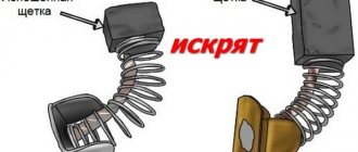
Starter brushes
Another development of events is also likely when the starting device has previously been repaired. The procedure for replacing the brushes this time was carried out incorrectly, the elements were accordingly placed in the wrong sequence. You need to test and determine where the brush with the “plus” polarity is facing. She should look directly opposite the "minus".
To determine the polarity of the brushes, simply attach them to each other. Accordingly, attraction or repulsion will help determine the correct polarity.
Incorrectly installed brushes are usually associated with the starter cover. It is placed incorrectly, which leads to polarity reversal (more on this below).
Types of faults in the electrical and mechanical parts of the drill
A malfunction of the electrical part manifests itself in the form of a lack of engine rotation, i.e. when there is no sign of the engine turning on (humming, vibration, etc.). If the impact drill does not turn on, and the chuck is easily turned by hand, then we can safely say that the electrical part is faulty. The same can be said if there is no speed control or reverse rotation. This indicates an expected malfunction in the electrical part. Temporary interruptions in the operation of the drill, extraneous noise may also indicate an electrical circuit.
Most often, a malfunction in the electrical part is due to wear on the contact brushes. If they are drained by 40%, then sparking and malfunctions may occur. If the brushes wear out more, the electric motor simply does not turn on. The following procedure for determining the culprit of an electrical fault is recommended (as available). First, the tester determines the integrity of the cord (cable). Then the operation of the start button (switch) and the integrity of the start capacitor are checked. Then the contact buttons are removed and checked. At the end, the integrity of the motor windings is determined.
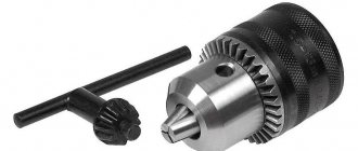
Drill chuck diagram.
A clear sign of a mechanical problem is a jammed drill shaft. If you cannot turn the cartridge by hand, and you can hear the hum of the electric motor when you turn it on, then the reason lies in the failure of the gearbox or bearing. The most common cause of mechanical failure is the destruction of support bearings. Gearbox failure can also occur when the chuck is turned by hand and the electric motor is running, but rotation is not transmitted to the main shaft. A mechanical malfunction can cause the drill to intermittently malfunction (temporarily stop), humming, grinding, and insufficient shaft rotation speed. In rotary hammers, a mechanical failure can eliminate the drill's impact motion.
Finally, the fault may appear in the drill chuck. Thus, difficulties may arise in removing the drill when the jaws do not move apart due to a breakdown in the engagement inside the chuck. Sometimes the malfunction manifests itself in the form of the chuck spinning relative to the drill shaft. In this case, the malfunction occurred in the area where the chuck is attached to the shaft.
Additional accessories
Using special devices for various purposes for a drill, you can expand the functionality of this universal tool. You need to purchase them separately, but you will never regret the money spent, because special attachments turn an ordinary drill into a grinder or mini-sharpener for home use. Using angle attachments, you can work with the tool in a hard-to-reach place or turn it into a metal cutter by installing an attachment with the original name cricket.
Special guides make it possible to work strictly at right angles; for vertical drilling, special jigs or factory-made stands are used, turning the drill into a drilling machine.
Regardless of which model the user uses, it requires constant care: after any, even short-term work, it is necessary to wipe the body of the product from any dust, paying special attention to the ventilation holes so that dust and small waste from drilling do not get inside the product.
If you are not going to use the drill for a long time, then all metal parts should be lubricated with a thin layer of technical oil - this will protect them from the effects of ubiquitous corrosion. Carry out periodic inspections of internal parts, especially for electric motor brushes - do not allow them to wear out to the limit. If you follow these recommendations, your instrument will not need repairs in the near future.
Any power tool consisting of electromechanical components, no matter how carefully it is treated, becomes unusable over time. This is largely due to mechanical components that require periodic lubrication.
Carrying out preventative maintenance or repairing a drill yourself is not so difficult if you are familiar with the structure of the tool and understand the principle of its operation.
Brushes
Another common problem with electric drills is wear on the motor brushes. When they are ground down by 40%, interruptions in the operation of the drill and even sparks can be detected. With an even greater degree of wear, the power unit simply will not start. Replacing outdated parts at home is not that difficult.
Some models have the ability to do electrical repairs yourself. drills (in particular, replacing brushes) without opening the case. There are special plugs for this. It is enough to unscrew them and replace the old worn brushes with new ones.
When choosing new parts, you should pay attention not only to their dimensions, but also to the cross-sectional profile
You should not allow the brushes to wear too much, as this can lead to a number of troubles. Firstly, the gap between them and the collector plates increases, which leads to increased sparking. Secondly, because of this, the plates become very hot, as a result of which they can move away from the base of the collector. This may result in the need to replace the armature.
Reversible drill functions
The drill mechanism includes an electric motor, a gearbox, a power regulator and a start button.
If a mechanism is additionally installed that allows for reciprocating movements back and forth, such a drill is called an impact drill. Modern drills have a function for adjusting the rotation speed; some models have a reverse function. The reversible drill is compact, safe, reliable, easy to use and lightweight. Its performance qualities allow it to be operated with one hand, as well as in places with limited access. Changing consumable materials is carried out very quickly thanks to the use of a high-quality quick-release chuck. Electronic adjustment maintains the required speed and ensures a slow start to drilling and further smooth operation at a frequency that is optimal for the material. A reversible drill can be used for drilling fragile materials, such as glass and tiles. In this case, the drill can be used as a screwdriver. Reversing also makes it easy to remove the drill if it gets jammed in the material; it is convenient to use for more uniform stirring of mixtures.
Diagnostics and troubleshooting of the electrical part of the screwdriver
If you have a battery-powered device, then the first thing you need to do is check the batteries in the battery pack by disassembling it. There are collapsible and non-dismountable blocks. In the second case, you will need to carefully insert a screwdriver into the place where the walls of the block are glued and, slowly, separate them.
Next, you need to measure the voltage on all “banks”. The voltage rating is indicated on the body of each battery. The voltage should be slightly lower than specified, but the same on working batteries. Faulty batteries will differ significantly from the rest in the voltage they produce - they will need to be replaced. New batteries can be purchased online.
If you are the owner of a networked screwdriver, then the verification algorithm is slightly different. First, you will need to unscrew the body of the device and remove one half of it. Take a tester and “ring” the power cord for a break. If the cord is working, you need to check the start button. With the button pressed, check whether there is a circuit at its output contacts. If the button is faulty, it will need to be replaced or repaired. How to do this will be discussed further. If the button is working properly, the problem may lie in the electric brushes or the motor.
Button repair
Below is an electrical diagram of a cordless screwdriver.
From the diagram you can see that 2 wires from the battery go to the button, and 2 wires come out of it to the engine. Also, 3 wires from the transistor responsible for adjusting the speed are connected to the button. To understand the structure of the screwdriver button, it must be disassembled. All wires going to this part do not need to be soldered. They will not interfere with disassembly.
Remove the push mechanism (red) from its seat. Do this with gentle rotational movements, while simultaneously pulling the part in the direction opposite to the button, making sure that the joke does not break.
Next, remove the button cover. In the places indicated by arrows in the figure, use a knife and a screwdriver to pry and push out the latches, and then remove the cover.
After removing the cover, you will see the reverse compartment. But the button mechanism will still be unavailable. Using a soldering iron, separate the 2 elements (indicated by an arrow in the following figure).
Carefully pull out element number 1, then remove the cover that covers the compartment with the device’s activation mechanism.
Holding the return spring, remove the mechanism from the housing.
In the faulty button you will see erased contact pads.
The contact pads wear out quickly due to the poor quality of the metal. Fine metal dust from actuated contacts accumulates between them and shorts out the pads. As a result, the device starts spontaneously.
Use cotton wool soaked in alcohol to remove metal dust. If this fails, you can scrape it off with a knife. After these steps, the spontaneous startup of the device will stop.
Replacing brushes
To check the condition of the brushes, it is necessary to disassemble the engine by bending the “antennae” located at the end of the housing.
Next, lightly tap the motor shaft with a hammer to knock the rotor out of the housing.
In this case, the cover in which the electric brushes are located will first be removed.
The next photo shows that the collector is black. This means that it will become contaminated with dust from the brushes. As a result of contamination of the commutator, as well as the grooves between its plates, engine power drops and the brushes spark. It is necessary to wipe the collector with cotton wool soaked in alcohol and clean the grooves with a needle.
The following photo shows what a clean manifold looks like.
If the brushes are worn out, they will need to be replaced. It is difficult to find original brushes on sale for some models of screwdrivers. But you can find brushes that are suitable in size, then use a sharpening machine to trim them and connect (solder) them to the brush holders.
To better understand how brushes are replaced, you can use the following video.
Engine brake repair
The engine brake is a device that stops the rotation of the armature when the start button is released. In screwdrivers, this function is implemented by closing the plus and minus of the motor when the button is released. As a result, a large self-induction occurs, and the spindle locks (with large sparks from under the brushes). If engine braking does not work, then the control transistor or start button will need to be replaced.
Connect a drill directly without a button: is it real?
You can repair a power tool such as a drill on your own at home, without resorting to outside help and without spending money on it. Often, during operation, the drill begins to work worse and stops starting.
The reason for the breakdown of an electric drill is wear of the brushes, failure of the motor and the start button. In this case, as a rule, the switch often breaks? due to which further use of the power tool becomes impossible.
To solve this problem, the old, faulty button is replaced or the electric drill is connected directly to the power supply.
Is it possible to connect a drill without a button?
A drill is one of the most used power tools in everyday life. Often, during its operation, an element such as the power button fails.
This is due to the fact that the switch responsible for turning the device on and off is subject to mechanical stress, as a result of which it quickly wears out.
It is for this reason that most people who use an electric drill have a completely logical question: is it possible to connect the drill directly without a power button and how to do it?
As a rule, in most cases, a similar question arises among people when the on/off switch of an electric drill fails, and it is not possible to purchase a new one.
It should be noted right away that it is quite possible to connect power to an electric drill and start it without a button.
However, during such a connection, you must follow all the rules and instructions for connecting the contacts of the device’s electric motor to the wires that supply power from the electrical network.
How to connect?
Connecting a drill directly to an electrical outlet without a switch is not as difficult a task as it might seem at first glance. Before you start connecting the electric drill and dismantling the power button, you need to stock up on the appropriate tools:
- screwdriver;
- soldering iron;
- insulating tape;
- sharp knife or blade (for stripping wires).
Before connecting the drill motor directly, the device's power button is removed.
To do this, use a screwdriver to unscrew the screws located on the side of the electric drill.
Then, after the screws have been removed, you need to dismantle (remove) one part of the power tool body. Then, when access to the switch is open, it must also be dismantled.
It is strongly recommended to solder the wires together using a soldering iron, and then the soldering points must be properly insulated using electrical tape.
As an alternative to soldering, you can use a terminal block (blocks), thanks to which the wires are connected to each other. You can also use a cambric to insulate the connection point.
The field winding consists of four wires. Two wires located diagonally from the coils must be connected to the wires that are connected to the brushes. The connection points must be insulated. Then the other two wires need to be connected to the power cord that powers the power tool.
If the electric drill chuck, after connecting the device to the power supply, starts to rotate in the wrong direction (reverse mode), then the connection wires just need to be swapped.
That is, the wires that go directly to the brushes need to be connected to the electrical network, and those contacts that were previously connected to the network need to be connected to the brushes.
Pros and cons of working without a button
When using an electric drill without a power button, there are many more disadvantages than advantages. The only advantage of such a power tool connection scheme is that there is no need to change or repair the switch. However, if the drill is connected directly to the network, many problems arise. For example, the functionality of the device suffers.
Without a switch, it is impossible to adjust the speed or turn on the reverse mode.
In addition, with this connection, the soft start function, which is equipped with most modern models of high-power electric drills, will not be available.
Also, before each use of the drill, you must constantly plug in the power cord and turn it off after completing the work, which is not entirely convenient.
In addition, the contact groups of the switch, when turning on the power tool, took on part of the load. If it is absent, both the motor winding and the brushes will be subject to increased load.
As a result, the motor of the power tool will wear out greatly and quickly fail.
How to use a drill
Drill bits are critical to how you use a drill. There are tools for working on metal, wood, concrete and stone materials. The drilling tool (drill) is clamped in a chuck, which can be conventional (with “jaws”) or quick-clamping. Drills for working on concrete have an insert made of tungsten carbide (“Pobedita”). They are designated "NM ST". When drilling a concrete wall, it is recommended to use the “impact” mode of the drill. To avoid breaking the drill, the tool must be held strictly perpendicular to the surface.
Since the surface of the wall, as a rule, is somewhat looser than the deeper layers, the drill can crumble it at the moment of impact, and the hole will shift from the intended point. To avoid this, you must first “punch” the hole, that is, use a hammer and a special core to make a recess. You can use a limit bar to adjust the drilling depth. If it is not available, you should wrap electrical tape around the drill. During work, cement dust and crumbs must be removed from the hole.
Metal drills are designated by the Latin letters HSS. When using them, you cannot turn on the “impact” mode; the drill may break. To make the drilling process faster, the metal surface should be pre-punched. Wood drills have edges sharpened parallel to the surface. In the middle of the tool there is a thin awl that allows the drill to punch the hole on its own. When drilling a hole, you need to monitor the rotation speed; at the first sign of smoke, the hole must be moistened with water. By switching the drill to reverse, you can remove chips from the hole. This function is activated by a flag switch located next to the start button.