Possible tool malfunctions - we carry out repairs ourselves
If your tool begins to work worse, or even stops performing its direct duties, it’s time to diagnose the problems and try to deal with them. First, we check the wire for damage and the voltage in the outlet, for which you can plug in any other device - a TV or a kettle.
If you are inspecting battery-powered devices, they should be checked using a tester - in this case, the voltage indicated on the case should have a similar value to the battery voltage.
If the voltage is less, you will have to replace the batteries with new ones. If the battery is working normally, the power supply is normal, look for hardware problems. The most common breakdowns are:
- Problems with engine operation;
- Brush wear;
- Problems with the button operation.
Knowing how the electric drill button is connected, you can quickly solve the problem. In addition, a problem with the operation of the drill can also arise due to the dustiness of the tool, because the drill “takes” wood, brick, and other materials. This means that you should take care to clean the device after each use - this is the only way to reduce the risk of malfunctions due to contamination of the tool. That is why, after you have carried out renovations in your apartment, immediately clean the drill.
How to reverse a power tool
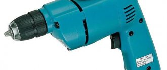
An electric drill is an irreplaceable thing that almost every man has. People who regularly use this tool periodically encounter it breaking down.
If it is not possible to take the device to a workshop, you will have to do the repairs yourself. In this case, you need to familiarize yourself with what the electric drill circuit looks like and understand the repair tips.
An electric drill is a device that is found in almost every home.
Possible tool malfunctions
First, you need to familiarize yourself with the main types of electric drill faults. They can be:
- Electric. Most often, breakdowns are related to electronics. There are times when the tool begins to spark due to overload. Some Bosch PSB models stop functioning due to the brushes grinding down.
- Mechanical. Sometimes bearings or gear mechanisms fail. In such situations, only complete replacement of broken parts will help.
Additional Information! The main signs of mechanical malfunctions include humming and a decrease in rotation speed.
Algorithm for finding and eliminating electrical failures
When searching for a breakdown, it is recommended to follow a certain algorithm that will help you quickly find the fault:
- If the device does not turn on completely, you need to open the case and check the cable connections. Perhaps one of them has become detached from the electrical circuit and therefore the device does not turn on.
- If everything is fine with the wires, you need to check the switch toggle switch. In some devices from Bosch and Makita, traces of oxidation appear over time and the device stops working.
- When inspecting the device, special attention should be paid to the brushes. They must press securely against the rotor.
Important! During inspection of the electric drill, do not connect it to the electrical network. Especially if the wire contacts are being checked.
Necessary tool
An ohmmeter is an indispensable tool for determining the causes of malfunctions.
Before you begin repairing an impact drill, you need to familiarize yourself with the list of tools that may be needed:
- pliers;
- ohmmeter;
- grinding sandpaper;
- vice;
- straight and Phillips screwdriver;
- spanners.
A vise may also be useful for securing some parts.
Types of drill button connection diagrams
There are two types of electric drill connection diagram. It is necessary to familiarize yourself with the features of each of them.
Wiring diagram for a shovel drill switch
The switch diagram will help you correctly connect the button to the tool.
As a rule, this scheme is used by craftsmen when repairing a broken tool. With its help, you can check all the functional features of the switch. It also allows you to carry out repairs after determining the cause of the breakdown.
Most manufacturers supply a circuit diagram for connecting the switch along with the instructions for the product. However, there are times when it is not there. In such situations, people have to search on the Internet on their own. To find it, you will have to find out the exact model of the device in advance.
Circuit with reverse and speed controller
The connection diagram for a switch with reverse is used to connect a reverse button
Some models from manufacturers such as Sparky or Interskol are equipped with switches with built-in speed control and reverse. It is quite difficult to understand such structures and therefore it is not always possible to determine the exact cause of their breakdown.
If such a button fails, it is recommended to simply buy a new one and connect it by referring to the diagram.
Let's get to the action - setting up the reverse
The two halves of the field winding of the electric motor are located on the stator. One wire goes from them to the brushes. Let's cut these wires.
It should be noted that the brushes vibrate during operation, so wires with increased flexibility were used to connect them. If you cut the wires close to the brushes, the flexible part will be short, and it may break due to vibration.
To prevent this from happening, we cut the wires closer to the field windings. We solder the wires to them that go to the moving contacts of switch S1.
We connect the terminals of the fixed contacts in accordance with the diagram and solder to them two wires going to the soft wires of the brushes.
Before soldering, the wires going to the toggle switch on one side (of the toggle switch or the electric motor) are inserted into the rubber bushing in advance. The task will be complicated by the fact that the tool’s power cord already passes through it.
Experienced executioners advise using a soap solution in such cases.
Don't have a drill yet? This article will help you choose the best model!
How to connect a button yourself
Many people are interested in how to properly connect the power button, since it is impossible to connect a drill without a button. This is done as follows:
- Disconnecting the switch.
- Cleaning darkened and rusty terminals from carbon deposits using sandpaper or alcohol.
- Replacing the speed controller if it is faulty.
- Assembling the button and its connection, according to the diagram of an electric drill with reverse and speed control.
Important! Before removing and connecting the button, you need to make sure that the electric drill is not connected to the outlet.
For example, if the power of your drill is W, then the regulator should easily operate at a current of 3.4 A. Electrical diagram for connecting wires and drill buttons. It is important to remember that the speed controller and the reverse control device are different parts.
Most often they are installed in different housings. As a rule, inexpensive models that are not intended for intensive use are purchased for household purposes.
How to detach the old button?
Unlike professional power tools, they have a short service life and often fail. One of the weakest points of a household drill is the start button. During operation, the contacts of the main control element often oxidize or burn out.
One of the main homemade tools is an electric drill, and the speed of work and quality depend on its design and convenience. I have a Soviet-made electric drill, which has served faithfully for many years. The metal gearbox housing and bearings in the gearbox made it almost indestructible!
If at one point the drill stops responding to pressing the start button or starts working every once in a while, do not rush to take the tool to a service center. Replacing the button on a drill is a fairly simple procedure that even a novice master can handle.
And so that no questions arise during the repair process, we have prepared simple and understandable instructions for you.
How to replace brushes and cartridge
Let us note in advance that any electric drill, regardless of manufacturer and model, consists of the same elements, so the instructions below are universal. The device of the drill button is very simple: when pressed, the button slides in a special block along the guides and the pusher closes the contacts, starting the electric motor.
During long-term operation under repair conditions, dust, moisture, etc. Therefore, before buying a new button, you should try to clean it. This defect can be eliminated very easily - you just need to open the block and remove dirt from it with a brush.
Checking the electric motor: causes of breakdowns and repairs
Drills, like many rotary hammers, often stop working due to motor failure. There are two reasons why it may fail:
- Incorrect use. Some people often overload the devices and therefore the motor stops working. In this case, it is easier to purchase a new drill.
- Bad coil wire. Most often, this problem occurs when using budget models. It is better not to replace the wire yourself. This is a job for professionals.
Replacing the Button on a Drill
Connection diagram Drilling buttons - repair the tool without the help of others!
Repairing the drill may not be possible, the main thing is to know the causes of failures and not their methods of “healing”. Now you will learn about the connection diagram of the buttons, we are here, we will not ignore other errors, because of which you will be the happy owner of a working tool.
Possible tool malfunctions - we carry out repairs ourselves
If your tool has become worse, as it is also called, and has completely stopped doing its direct duties, it’s time to diagnose errors and try to cope with it. That's it, we check the wire for any damage or voltage in the socket, for which you can turn on any other device - a TV set, in other words, a kettle.
If you are testing battery-powered devices, they should be inspected using a tester - in such circumstances, the voltage indicated on the case must be the same value as the battery voltage.
If the voltage is less, you will have to replace the batteries with new ones. If the battery is working normally, the power supply is normal, look for problems with the equipment. More common mistakes are:
Drill button connection diagram - how to fix the problem?
Unfortunately, to check the functionality of the tool, a tester will not be enough for you, which is due to the fact that most of the device’s buttons are equipped with smooth speed control, and therefore a regular tester may give you incorrect data. In this case, you will need a special connection diagram for the drill button. Often in instruments one wire is connected to a terminal, and therefore pressing the button simultaneously leads to ringing of the terminals. If the light comes on, everything is fine with the button, but if you notice a malfunction, it’s time to replace the button.
When making a replacement, keep in mind that the circuit can be either simple or with reverse. Due to this, all work on replacing the button must be carried out exclusively according to the diagram, without adding anything “on your own”. So, the part must be suitable in size and match the power of the tool. At the same time, calculating power is a fairly simple task. We use the formula P=U*I (taking into account that the drill power is 650 W), I = 2.94 A (650/220), which means the button should be at 2.95 A.
Electric drill: device diagram
For example, remember that opening the case may cause all parts and loose parts to simply fall out of the case. Naturally, this should be avoided, because then it will be quite difficult to assemble the device together. To do this, you can smoothly lift the cover, noting the exact location of the spare parts on paper.
The button is repaired as follows:
- First, the clamps for the casing are hooked, after which it is carefully pulled together;
- All rusted and darkened terminals are cleaned of carbon deposits, for which you can use alcohol or sandpaper;
- We reassemble the tool, making sure that all parts of the device are in place, and check the functionality of the drill - if nothing has changed, we change the part;
- We fill the speed regulator with a compound, and therefore if a part fails, we simply replace it;
- A frequent breakdown is the abrasion of the working layer under the rheostat - it’s better not to repair it, it’s just a waste of time, it’s better to buy a new one and replace it.
Many people are interested in where to get such a scheme? First of all, it should come with the instrument when you purchase it, but if there is no diagram or you have lost it, you will have to look on the Internet. After all, only with its help will you be able to carry out repairs competently, without errors. By the way, the speed control button and the reverse control button are located in different places, and therefore you will have to check them separately.
DIY drill repair | Master Vintik. Everything with your own hands!
If you have certain skills, repairing a drill at home is quite simple. From the numerous cases of drill breakdowns, several characteristic malfunctions can be identified, which are caused by improper operation of the power tool or defective elements from the manufacturer. Such typical breakdowns include:
- failure of engine elements (stator, armature);
- brush wear or burnt;
- breakdown of the regulator and reverse switch;
- wear of support bearings;
- poor quality clamp in the tool chuck.
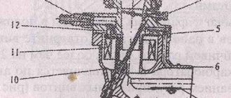
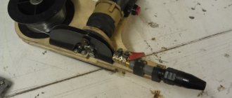
Drill structure (the simplest Chinese electric drill):
1 — speed regulator, 2 — reverse, 3 — brush holder with brush, 4 — motor stator, 5 — impeller for cooling the electric motor, 6 — gearbox.
Electric drill structure: 1 - stator, 2 - stator winding (second winding under the rotor), 3 - rotor, 4 - rotor commutator plates, 5 - brush holder with brush, 6 - reverse, 7 - speed controller.
Replacing brushes
The most common type of breakdown is wear of the motor brushes, which can be replaced yourself at home. Sometimes, brushes can be replaced without disassembling the drill body.
For some models, it is enough to unscrew the plugs from the installation windows and install new brushes.
For other models, replacement requires disassembling the housing; in this case, you must carefully remove the brush holders and remove the worn brushes from them.
Brushes are sold at all normal power tool stores, and often an extra pair of brushes is included with a new electric drill.
New brushes
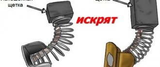
Don't wait for the brushes to wear down to their minimum size. This risks increasing the gap between the brush and the collector plates. As a result, increased sparking occurs, the collector plates become very hot and may “move away” from the base of the collector, which will lead to the need to replace the armature.
You can determine the need to replace brushes by increased sparking, which can be seen in the ventilation slots of the housing. The second way to determine this is the chaotic “jerking” of the drill during operation.
Power cord
The cord is checked with an ohmmeter, one probe is connected to the contact of the power plug, the other to the core of the cord. Lack of resistance indicates a break. In this case, repairing the drill comes down to replacing the power cord.
Electric motor diagnostics
In second place, in terms of the number of drill breakdowns, can be placed the malfunction of engine components and, most often, the armature. Failure of an armature or stator occurs for two reasons - improper operation and poor-quality winding wire.
World-famous manufacturers use expensive coil wire with double insulation with heat-resistant varnish, which significantly increases the reliability of engines. Accordingly, in cheap models the quality of insulation of the winding wire leaves much to be desired.
Improper operation comes down to frequent overloading of the drill or prolonged operation without breaks to cool the engine. Repairing a drill with your own hands by rewinding the armature or stator, in this case, is impossible without special tools.
Only complete replacement of the element (exclusively experienced repairmen will be able to rewind the armature or stator with their own hands).
To replace the rotor or stator, it is necessary to disassemble the housing, disconnect the wires, brushes, remove the drive gear if necessary, and remove the entire motor along with the support bearings. Replace the faulty element and install the engine in place.
An armature malfunction can be determined by a characteristic smell, an increase in sparking, and the sparks have a circular motion in the direction of movement of the armature. Pronounced “burnt” windings can be seen upon visual inspection. But if the engine power has dropped, but there are no signs described above, then you should resort to the help of measuring instruments - an ohmmeter and a megohmmeter.
Windings (stator and armature) are subject to only three damages - interturn electrical breakdown, breakdown to the “case” (magnetic circuit) and winding breakage. A breakdown to the housing is determined quite simply; it is enough to touch any winding output and magnetic circuit with the probes of a megohmmeter.
A resistance of more than 500 MΩ indicates no breakdown. It should be taken into account that measurements should be carried out with a megger with a measuring voltage of at least 100 volts.
By taking measurements with a simple multimeter, it is impossible to accurately determine that there is definitely no breakdown, but you can determine that there is definitely a breakdown.
It is quite difficult to determine the interturn breakdown of the armature, unless, of course, it is visible visually. To do this, you can use a special transformer, which has only a primary winding and a break in the magnetic circuit in the form of a trench for installing an armature into it.
In this case, the armature with its core becomes a secondary winding. Rotating the armature so that the windings alternate in operation, we apply a thin metal plate to the armature core.
If the winding is short-circuited, the plate begins to rattle strongly, and the winding heats up noticeably.
Often, an interturn short circuit is detected in visible areas of the wire or armature bar: the turns may be bent or wrinkled (i.e.
pressed against each other), or there may be some conductive particles between them.
If so, then it is necessary to eliminate these short circuits by correcting bruises in the tire or removing foreign bodies, respectively. Also, a short circuit can be detected between adjacent collector plates.
You can determine whether the armature winding is broken if you connect a milliammeter to the adjacent armature plates and gradually turn the armature. In whole windings a certain identical current will appear; a broken winding will show either an increase in current or its complete absence.
A break in the stator windings is determined by connecting an ohmmeter to the disconnected ends of the windings; the absence of resistance indicates a complete break.
Speed controller and reverse
The presence of voltage at the input terminals of the power button and absence at the output terminals indicates a malfunction of the contacts or components of the speed controller circuit.
You can disassemble the button by carefully picking up the latches of the protective casing and pulling it off the button body. A visual inspection of the terminals will allow you to judge their performance. Blackened terminals are cleaned of carbon deposits with alcohol or fine sandpaper.
Then the button is reassembled and checked for contact; if nothing has changed, then the button with the regulator must be replaced. The speed controller is made on a substrate and is completely filled with an insulating compound, so it cannot be repaired.
Another typical malfunction of the button is the erasure of the working layer under the rheostat slider. The easiest way out is to replace the entire button.
Repairing a drill button with your own hands is only possible if you have certain skills. It is important to understand that after opening the case, many switching parts will simply fall out of the case. This can be prevented only by smoothly lifting the cover initially and sketching the location of the contacts and springs.
The reverse device (if it is not located in the button body) has its own changeover contacts, and therefore is also susceptible to contact loss. The disassembly and cleaning mechanism is the same as the buttons.
When purchasing a new speed controller, you should make sure that it is designed for the power of the drill, so with a drill power of 750W, the regulator must be designed for a current of more than 3.4A (750W/220V=3.4A). And by the way, the regulator of the drill in the photo is not original, and in order for it to fit into the body, the lower part of the trigger was cut off.
The lower part of the trigger is cut off
The wiring diagram, and in particular the drill button connection diagram, may differ in different models. The simplest diagram, and best demonstrating the principle of operation, is the following. One lead from the power cord is connected to the speed controller.
Electrical diagram of a drill. "reg. rev." — electric drill speed regulator, “1st rotation station.” - first stator winding, “2nd stator winding.” - second stator winding, “1st brush.” - first brush, “2nd brush.” - second brush.
To avoid confusion, it is important to understand that the speed controller and the reverse control device are two different parts that often have different housings.
The speed controller and reverse are located in separate housings. The photo shows that only two wires are connected to the speed controller.
The only wire coming out of the speed controller is connected to the beginning of the first stator winding. If there were no reversing device, the end of the first winding would be connected to one of the rotor brushes, and the second rotor brush would be connected to the beginning of the second stator winding. The end of the second stator winding leads to the second wire of the power cord. That's the whole scheme.
A change in the direction of rotation of the rotor occurs when the end of the first stator winding is connected not to the first, but to the second brush, while the first brush is connected to the beginning of the second stator winding.
Drill reverse circuit
This switching occurs in the reverse device, so the rotor brushes are connected to the stator windings through it. This device may have a diagram showing which wires are connected internally.
Diagram on the reverse of an electric drill (in the photo the reverse is disconnected from the speed controller)
Electric drill reverse connection diagram
Black wires lead to the rotor brushes (let the 5th contact be the first brush, and let the 6th contact be the second brush), gray wires lead to the end of the first stator winding (let there be the 4th contact) and the beginning of the second (let there be 7- th contact).
When the switch is in the position shown in the photo, the end of the first stator winding with the first rotor brush (4th with 5th), and the beginning of the second stator winding with the second rotor brush (7th with 6th) are closed.
When switching the reverse to the second position, the 4th is connected to the 6th, and the 7th to the 5th.
The design of the electric drill speed controller provides for connecting a capacitor and connecting both wires coming from the outlet to the controller. The diagram in the figure below, for better understanding, is slightly simplified: there is no reverse device, the stator windings to which the wires from the regulator are connected are not yet shown (see diagrams above).
Connection diagram for the button (speed control) of the drill.
In the case of the electric drill shown in the photo, only two lower contacts are used: the far left and the far right. There is no capacitor, and the second wire of the power cord is connected directly to the stator winding.
Connecting an electric drill button
Read about the principle of operation of the speed controller in the article about the device of a drill.
Gearbox
The presence of extraneous sounds, grinding and jamming of the cartridge indicates a malfunction of the gearbox or gear shift mechanism, if any. In this case, it is necessary to inspect all gears and bearings. If worn splines or broken teeth are found on the gears, then a complete replacement of these elements is necessary.
Bearings are checked for suitability after removing them from the armature axis or drill body using special pullers. While holding the inner race with two fingers, you need to rotate the outer race.
Uneven slipping of the race or “rustling” when scrolling indicates the need to replace the bearing.
A bearing replaced at the wrong time will lead to jamming of the armature, or, in the best case, the bearing will simply turn in the seat.
Replacing the drill chuck
The chuck is subject to wear, namely the clamping jaws, due to dirt and abrasive residues of building materials getting into it. If the cartridge needs to be replaced, it is necessary to unscrew the retaining screw inside the cartridge (left-hand thread) and unscrew it from the shaft.
In conclusion, I would like to add: when assembling the drill after repairing it, make sure that the wires are not pinched by the top cover. If everything is in order, the two halves will collapse without a gap. Otherwise, when tightening the screws, the wires may become flattened or cut.
Flattened wire.
Source: tool-land.ru
- Second life of an old electricity meter
- We repair a shovel.
Old induction household electricity meters are no longer needed - they no longer provide accurate metering and are being replaced by electronic ones. Their fate is the trash heap or a shelf in the garage, “just in case.” We will try to give a second life to the hard worker. I propose to make a portable lamp in a durable and lightweight meter housing.
Read more…
Checking the electric motor: causes of breakdowns and repairs
There are several reasons for damage to the armature or stator of a drill. First of all, this is illiterate operation of the device. For example, many users simply overload the tool, working without interruption. This leads to the fact that the drill motor does not have time to “rest”. The second reason lies in poor coil wire, which is often found in cheap models. That is why breakdowns of cheap tools are much more common. In this case, repairs must be carried out using specialized tools. And it will be better if you entrust this work to professional specialists.
However, if you decided to carry out the repairs on your own, you will definitely have a question - how to do everything right? As you already understand, an electric drill “suffers” from damage to the armature and stator, and this can be checked with several signs, for example, when the tool suddenly sparks during operation. If there are no “bright” signs, you can use an ohmmeter.
The stator is changed like this:
- First, carefully disassemble the device body;
- Remove the wires and all internal parts;
- After finding out the causes of the breakdown, we replace the spare part with a new one and close the housing again.
How to replace brushes: work in a couple of minutes
But the drill may not work due to trivial faults - for example, due to brushes inside the motor. This means that you can’t do without repairing brushes, and this work is quite simple - you don’t even need to have special knowledge and tools. To do this, we disassemble the device, remove the brush holders from it and replace parts that are broken. By the way, there are models whose body does not need to be disassembled - you just need to remove special plugs through the installation window, after which we change the brushes.
You can purchase these parts at any hardware store; there are also some models that are sold along with a set of additional brushes. It is important that you do not wait until the brushes are completely worn out - check them from time to time. And all due to the fact that there is a risk of a gap forming between the bristles and the collector. As a result, this part will begin to overheat and eventually fall off - which means you will have to change the entire anchor, which will be much more expensive and more difficult, and it is not a fact that you will be able to solve this issue yourself.
As you can see, there are a variety of breakdowns, many of which will be within your control, others will only be possible for specialists in service centers. And to reduce the risk of such breakdowns, you need to take care of your tool, clean it after work, check the condition of the parts and brushes in order to replace them with new ones in time. However, if you see that you can’t handle it yourself, take the device to a workshop.
Triac regulator
The triac controller located in the start button is responsible for the speed of the installation when the drill is turned on. This regulator is mounted in the button body and is located on a lining made of textolite. The board is designed in such a way that it has small dimensions, which allows it to be completely located in the trigger space. After pressing the power button, an immediate break occurs in the device regulator, at which point the circuit is closed in a scanty period of time. And the regulator is not able to influence the voltage variation, however, the rms voltage level is subject to change.
After the drill starts operating, alternating voltage is supplied to the network.
Figure 2. Drill spare parts.
In parallel with this, a sinusoidal voltage is supplied to the control electrode of the triac. During the period when its level is greater than the operating voltage of the triac, the latter opens, which indicates the circuit is closed; at this moment, current flows through the load.
The wiring diagram and connection of the installation button may differ in different models from different manufacturing plants. The most simplified of all the diagrams and the one that best shows the principle of operation is shown in Fig. 3. One wire from the power cord is connected to the speed controller. The presented figure shows the electrical circuit of the device, where “reg. rev." – speed regulator, “1st stage” exchange." – primary stator winding, “2nd st. winding.” – respectively, secondary, “1st brush.” - first brush.
In order not to get confused, it should be remembered that the speed controller and the reverse control system are represented by completely different components of the tool, which in some models even have separate housings.
Figure 3. Typical diagram of a drill speed controller.
Only 2 wires go to the speed controller. And the one that comes out of the speed controller is connected to the beginning of the stator primary. In the absence of reverse, the end of the primary would be mated to the rotor brush, and the second brush would be mated to the beginning of the stator secondary. The end of the secondary goes to the second wire of the cord, from which the drill is powered during operation.
The rotor begins to work in the other direction the moment the end of the primary is connected to the second brush. In the reverse system, such a connection is made; for this reason, the rotor brushes are interfaced with the stator windings through it. In Fig. Figure 4 shows a connection diagram for the reverse device. Wires in the amount of 4 pcs. go to the rotor brushes, those of them that are gray in color go to the end of the primary and the beginning of the secondary.
The system for adjusting the speed of the device involves the presence of a capacitor and the connection of wires that come from the outlet to the regulator. If we take into account the installation from the example, then only two contacts are used, which are located at the bottom. The system is completely devoid of a capacitor, and the second wire of the cord is connected directly to the stator winding.