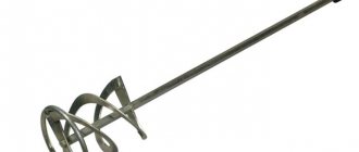
Screwdriver speed controller
An electric screwdriver operates either from a 220 V network or from a rechargeable battery. Its power depends on the battery voltage. The screwdriver rotation speed starts at 15,000 rpm. In addition, a powered screwdriver has 2 rotation speeds: a slower one for screwing, a higher one for drilling. The speed control is located inside the power button. The rather miniature size of this tool assembly is achieved using microfilm technology. Its main part is a triac. The operating principle of the regulator is as follows:
- When the button is turned on, an alternating current having a sinusoidal phase is supplied to the control electrode of the triac.
- The triac opens and current begins to pass through the load.
The response time of the triac depends on the amplitude of the control voltage. The greater the amplitude, the earlier the triac is triggered. The amplitude value is set using a variable resistor connected to the start button. The button connection diagram differs in different models. It is possible to connect a capacitor to the speed controller.
Often, in the current economic conditions, the buyer cannot always afford a full-fledged expensive screwdriver from reputable companies. Cheaper models may not have this feature. But this is no reason to despair. You can assemble the speed controller yourself, which we will talk about below.
The screwdriver speed controller is assembled on the basis of a PWM controller and a key multi-channel field-effect transistor. The operation of this tool unit is controlled by a resistor. Its position depends on the pressure on the screwdriver start button.
The direction of rotation of the working body changes by changing the poles of the voltage that is supplied to the motor brushes. This is done instrumentally using changeover contacts actuated by a reverse lever.
It is possible to assemble such a regulator with your own hands. We will look at how to do this below.
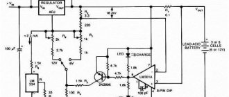
A diagram of the elements that make up the speed controller is shown in the figure below.
In this case, a dual comparator microcircuit LM 393 is used. Here, the first comparator works as a sawtooth voltage generator, and the second one is PWM. The control signal for PWM is the voltage drop across the motor contacts. To put it simply, in the diagram the electric motor looks like active and inductive resistances connected in series with each other. When the load changes, the ratio of these resistances changes accordingly, the regulator controls this and changes the PWM filling, thereby stabilizing the speed.
An electronic transformer should be used as the power source for PWM. It is a half-bridge voltage converter from 220 to 12 V, which is used to power halogen lighting lamps. Its dimensions are comparable to the size of a matchbox. The price fluctuates between 2–3 USD. e. It is necessary to add a rectifier to the output (these are four diodes, for example, KD 213), as well as a capacitor with a capacity of several thousand microfarads at 25 volts. All this will constitute a switching power supply with a constant output voltage.
We should also talk about making a printed circuit board for the regulator. To make it you need a sheet of photo paper and a laser printer. First you need to print the design on photo paper using a laser printer, then transfer it to the board blank using a heated iron. The board blank with the paper attached is placed in a container and placed under a stream of hot water. This is done so that the gelatin layer of the photo paper swells and it peels off from the board. The remaining pattern on the board is etched with ferric chloride.
Execution of work
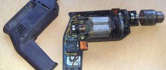
The reason for the repair was the unstable operation of the power button. When fully pressed, the screwdriver motor stopped working.
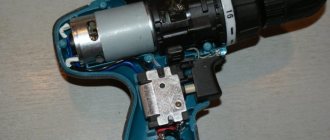
To diagnose the malfunction, it is necessary to disassemble the screwdriver body. To do this, remove the battery and use a flat screwdriver to remove the decorative trim on the case (under it there are screws that secure the case). The pads are secured with plastic fasteners, which break quite easily.
Using a Phillips-head screwdriver, unscrew the screws securing the case (in our case, 8 screws) and carefully disassemble the case.
When opened, it is clear that the power transistor is melted. The transistor is involved in the circuit for smooth control of the screwdriver speed. When the button is pressed fully, the motor power circuit is closed directly, ensuring operation at full power. Most likely the problem is in the button.
It is necessary to ensure that the engine is in good working order. To do this, disconnect the two motor power wires from the button, pull them out and press the spring contact of the button with a narrow flat-head screwdriver.
In order to get to the second wire, remove the battery contacts and the button from the grooves in the screwdriver body.
We connect the screwdriver motor to the battery contacts (polarity is not important). Checking the rotation.
If the engine is working properly, the button needs to be replaced. It is important to choose a button specifically for a given screwdriver, since not all buttons can fit into the grooves in size. The button is sold complete with battery terminals and transistor.
We connect a new button.
To do this, connect the motor to the button terminals. At this stage, the polarity of the connection is not important.
We connect the battery contacts of the new button to the battery.
Press the button and check the direction of rotation of the motor. Pay attention to the position of the direction switch lever. This is necessary in order to select the position of the rotation direction selection button that is familiar to you. If the position does not match, it is enough to swap the two wires from the engine with each other.
We assemble the screwdriver body in reverse order. We insert the plastic pusher into its groove and connect it to the button lever. We install the battery contacts into the groove of the housing.
We install the transistor with an aluminum plate in the groove.
Carefully place the wires in the housing, taking into account all the grooves and latches. This is necessary to avoid breaking the wires during reassembly. The housing should assemble easily and effortlessly.
We tighten the housing mounting screws with a little force and install the plastic cover.
Screwdriver force regulator
The force regulator is a clutch that limits the force when the chuck rotates. It is made in the form of a rotating plastic drum. The amount of tightening is adjusted using a digital scale located around the circumference of the drum. By increasing the tightening value, you screw the screw in deeper.
This function will be necessary when working with material products of varying degrees of hardness, since when working with soft material, the body of the self-tapping screw will be easily recessed into it; too high a hardness of the material will contribute to the violation of the geometry of the screw, especially if it is small in size. The ratchet, as the regulator is also called, prevents cutting off the splines of the screws, as well as wear on the screwdriver attachments. The adjusting ring should be tightened in stages, starting with the slightest force. In those screwdrivers in which drilling can be done, the last pictogram on the ring will be in the form of a drill. In this position, maximum torque is achieved.
Electronic screwdriver speed control
The rotation speed of the screwdriver attachment can be adjusted mechanically or automatically. Automatic speed control occurs using a processor. You can set the desired operating parameters using the speed selection toggle switch. It is located on top of the body. In many models, speed control is realized through the start button. The stronger the finger pressure on it, the higher the speed will be.
After reading this article, you received information on how to assemble a screwdriver speed controller with your own hands, became familiar with the design of the force regulator, and understood the function of electronic adjustment of the tool. We hope you found the article useful.
Source: pro-instrument.com
Required materials and tools
The materials and tools when remaking a screwdriver completely depend on the type of tool and the type of power source, as well as its features. But if we generalize, we can highlight several main tools:
How to save on repairing buttons for a BOSCH screwdriver
- screwdrivers;
- pliers;
- knife;
- insulating materials;
- cable for supplying electricity;
- soldering iron and materials for soldering;
- some kind of housing for the future power supply.
Communities › Electronic Crafts › Blog › My micro drill and automatic speed controller.
Good day to everyone reading this post! Prologue
.
I understand that most of the participants in this community are seasoned “electronic” wolves, but suddenly my post will still be useful to someone...
Recently I have become a little interested in radio electronics, not least because of the appearance of the car. Having made a couple of printed circuit boards to control the battery charge (one, two), I realized that I no longer wanted to drill millimeter holes with a screwdriver. And I began to study the hardware on the topic of microdrills for printed circuit boards. I re-read a bunch of forums, watched gigabytes of videos and went into the bins. And in the bins they found a power supply from an inkjet printer (24V/1A) that had served faithfully for ten years and two motors from it labeled QK1-0889. No matter how hard I searched, I still couldn’t find the exact datasheet for this motor. But it spins very quickly from this power supply. I measured the shaft (2.3 mm) and ordered a collet chuck with a set of collets on AliExpress. While the kit was on the way, I continued to learn the intricacies of drilling printed circuit boards. And so, I came across an automatic speed controller. I will say right away that there are a great variety of regulators for microdrills. I decided to go from simple to complex.
Types of bits for a screwdriver: how to choose
To choose the right nozzles, you need to study their varieties. First determine the shank shape type and diameter. It ranges from 1/4 to 1 inch.
- basic;
- special;
- combined.
Read also: Blacksmithing for beginners
Types of main bits:
- splined. They differ in the width and thickness of the slot;
Spline bits of different widths and thicknesses
Types of special bits:
- tri wing or triangular;
Double pin have a notch
The drywall bit has a stop stop
Spring Lock Bit
Combination bits have two types of shank shapes or one, but of different sizes. For example, a splined shank and sprocket.
Example of a combination nozzle
Splined shank and sprocket
Determine the length of bit you need for the job. It ranges from 10 to 200 mm.
Depending on the shape of the shank, the nozzles have a certain marking:
- Sl (Slot) – splined;
- Ph (Philips) – cross-shaped universal;
- Pz (Poz >An important characteristic is the grade of steel from which the bat is made. The nozzle may have a protective coating. The strength of the equipment depends on this. The main types of steel and coatings that should be given preference:
- Cr-v - chrome vanadium steel. The most common, with increased hardness;
- Cr-Mb - chromium-molybdenum steel. Less common. Very durable material;
- Ni - nickel coating. Increases resistance to corrosion;
- WC - tungsten carbide coating. Increases strength;
- Tin - titanium nitrite yellow coating. Increases strength.
Tin - coating for increased strength
Nozzles vary depending on the purpose:
- twisting and unscrewing;
- drilling;
- riveting;
- polishing;
- milling.
Considering all the parameters considered, you can easily select the necessary bits.
Drill speed controller diagram
All modern drills are produced with engine speed regulators built into them, but for sure, in the arsenal of every radio amateur there is an old Soviet drill, in which the change in speed was not intended, which sharply reduces the performance characteristics.
Speed controller circuit for a Soviet drill
The figure below shows a diagram of a speed controller for an electric drill motor, assembled as a separate external unit and suitable for any drills with a power of up to 1.8 kW, as well as for other similar devices that use a commutator AC motor, for example, in grinders. The regulator parts in the diagram are selected for a typical drill with a power of about 270 W, 650 rpm, voltage 220V.
The thyristor type KU202N is mounted on a radiator for the purpose of its normal cooling. To set the desired rotation speed of the electric motor, the regulator cord is connected to a 220 V power outlet, and the drill is plugged into it. Then, by moving the variable resistance knob R, set the required speed for the old drill.
Angler speed controller circuit diagram
The presented circuit is simple enough to be repeated even by a novice radio amateur. The components and parts required for assembly are cheap and easily available. It is recommended to assemble the structure in a separate box with a socket. Such a device can be used as a portable device with a standard power regulator
Speed regulator of a homemade micro drill
The operating principle of this amateur radio homemade product is as follows: when the load is small, the current flows small, and as soon as the load increases, the speed gradually increases.
The LM317 microassembly must be installed on the radiator. 1N4007 diodes can be replaced with similar ones designed for a current of at least 1A. The printed circuit board is made on single-sided fiberglass. Resistance R5 with a power of at least 2W, or wire.
The 12V power supply should have a small current reserve. Using resistor R1 we set the required idle speed. Resistance R2 is necessary to set the sensitivity to the load; it sets the required torque for increasing the speed of the microdrill. If you increase the capacity of C4, the high speed delay time increases.
Micro Drill Speed Controller for Drilling Small Holes in PCBs
The circuit presented below allows you to assemble a very simple, cheap and useful speed controller for a 12-volt microdrill for drilling holes in printed circuit boards in amateur radio practice.
The LM555 microassembly is used as a pulse width modulator. The supply voltage for PWM is reduced and stabilized using the LM7805 chip). Precision tuning resistor P1 of 50 KOhm allows you to adjust the rotation speed of the drill. The IRL530N field-effect transistor is used as an output drive element and can switch current up to 27A. In addition, it has fast switching times and low resistance. The 1N4007 diode is needed to protect against counter EMF. As an alternative, you can take the MBR1645 Schottky diode.
PWM (Pulse Width Modulation) used in this design is an effective method of varying speed and power for all DC motors.
PWM speed controller
Let's look at the first 5 amp PWM regulator. There is such a favorite microcircuit of all radio amateurs - this is the NE555 timer (or the Soviet analogue KR1006VI). It is on this chip that the PWM regulator is assembled. In addition to the timer, here I use a 9 volt stabilizer LM7809, a powerful N-channel field effect transistor IRF540, a dual Schottky diode, as well as other small parts. The circuit by which this regulator is assembled is known to everyone and is very popular.
The signet of this board can be downloaded - PWM 5A
In a more powerful design, I simply use parallel connection of several IRF540 field-effect transistors and a more powerful dual Schottky diode. Otherwise everything is the same.
The signet for this board can be downloaded - PWM 10A Connecting the PWM controller is very simple. You see 4 terminals - two terminals for power supply and , and two terminals for connecting the motor and . I also made a PWM controller with current protection. For these purposes, I used the common operational amplifier LM358 and two PC817 optocouplers. When the current that we set with trimmer R12 is exceeded, the trigger-latch on the op-amp DA3.1, optocouplers DA4 and DA5 is triggered and the generation of pulses on the 5th leg of the NE555 timer is blocked. To start generation again, you need to briefly remove power from the circuit using the S1 button.
The seal of this board can be downloaded - PWM 10A with protection. The PWM regulators are all operational, I checked their operation using a motor from a screwdriver. Made a video -
Excellent Youtube affiliate - https://join.air.io/roshansky
Source: i-perf.ru
The 555 timer is widely used in control devices, for example, in PWM speed controllers for DC motors.
Anyone who has ever used a cordless screwdriver has probably heard a squeaking sound coming from inside. This is the whistling of the motor windings under the influence of the pulse voltage generated by the PWM system.
It is simply indecent to regulate the speed of an engine connected to a battery in another way, although it is quite possible. For example, simply connect a powerful rheostat in series with the motor, or use an adjustable linear voltage regulator with a large radiator.
A variant of the PWM regulator based on the 555 timer is shown in Figure 1.
The circuit is quite simple and is based on a multivibrator, albeit converted into a pulse generator with an adjustable duty cycle, which depends on the ratio of the charge and discharge rates of capacitor C1.
The capacitor is charged through the circuit: +12V, R1, D1, the left side of the resistor P1, C1, GND. And the capacitor is discharged along the circuit: upper plate C1, right side of resistor P1, diode D2, pin 7 of the timer, bottom plate C1. By rotating the slider of resistor P1, you can change the ratio of the resistances of its left and right parts, and therefore the charging and discharging time of capacitor C1, and, as a consequence, the duty cycle of the pulses.
Figure 1. PWM circuit - regulator on a 555 timer
This scheme is so popular that it is already available in the form of a set, as shown in the following figures.
Figure 2. Schematic diagram of a set of PWM regulators.
Timing diagrams are also shown here, but, unfortunately, the part values are not shown. They can be seen in Figure 1, which is why it is shown here. Instead of bipolar transistor TR1, without altering the circuit, you can use a powerful field effect one, which will increase the load power.
By the way, another element has appeared in this diagram - diode D4. Its purpose is to prevent the discharge of the timing capacitor C1 through the power source and load - the motor. This ensures stabilization of the PWM frequency.
By the way, with the help of such circuits you can control not only the speed of a DC motor, but also simply an active load - an incandescent lamp or some kind of heating element.
Figure 3. Printed circuit board of a set of PWM regulators.
If you put in a little work, it is quite possible to recreate this using one of the programs for drawing printed circuit boards. Although, given the small number of parts, it will be easier to assemble one copy using a hinged installation.
Figure 4. Appearance of a set of PWM regulators.
True, the already assembled branded set looks quite nice.
Here, perhaps, someone will ask a question: “The load in these regulators is connected between +12V and the collector of the output transistor. But what about, for example, in a car, because everything there is already connected to the ground, the body, of the car?”
Yes, you can’t argue against the mass; here we can only recommend moving the transistor switch to the gap in the “positive” wire. A possible version of such a scheme is shown in Figure 5.
Figure 6 shows the MOSFET output stage separately. The drain of the transistor is connected to +12V of the battery, the gate simply “hangs” in the air (which is not recommended), a load is connected to the source circuit, in our case a light bulb. This figure is shown simply to explain how a MOSFET transistor works.
In order to open a MOSFET transistor, it is enough to apply a positive voltage to the gate relative to the source. In this case, the light bulb will light up at full intensity and will shine until the transistor is closed.
In this figure, the easiest way to turn off the transistor is to short-circuit the gate to the source. And such a manual closure is quite suitable for checking the transistor, but in a real circuit, especially a pulse circuit, you will have to add a few more details, as shown in Figure 5.
As mentioned above, an additional voltage source is required to turn on the MOSFET transistor. In our circuit, its role is played by capacitor C1, which is charged via the +12V circuit, R2, VD1, C1, LA1, GND.
To open transistor VT1, a positive voltage from a charged capacitor C2 must be applied to its gate. It is quite obvious that this will only happen when transistor VT2 is open. And this is only possible if the optocoupler transistor OP1 is closed. Then the positive voltage from the positive plate of capacitor C2 through resistors R4 and R1 will open transistor VT2.
At this moment, the input PWM signal must be at a low level and bypass the optocoupler LED (this LED switching is often called inverse), therefore, the optocoupler LED is off and the transistor is closed.
To turn off the output transistor, you need to connect its gate to the source. In our circuit, this will happen when transistor VT3 opens, and this requires that the output transistor of the optocoupler OP1 be open.
The PWM signal at this time is at a high level, so the LED is not shunted and emits the infrared rays assigned to it, the optocoupler transistor OP1 is open, which as a result turns off the load - the light bulb.
One of the options for using such a scheme in a car is daytime running lights. In this case, motorists claim to use high beam lamps turned on at full intensity. Most often, these designs are on a microcontroller; there are plenty of them on the Internet, but it’s easier to do it on an NE555 timer.
Source: electric.info
Article rating:
Save to:
Screwdriver speed controller diagram Link to main publication