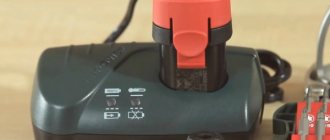
Operating mode switch
Removing the cartridge.
Cartridge.
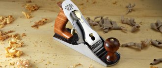
Makita HR 2450
November 11, 2011
Disassembling the hammer drill is carried out in the following order: first remove the cartridge, then the mode switch
work then you can unscrew the screws holding the engine to the gearbox.
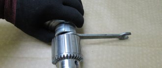
You don't need any tools other than a flathead screwdriver to remove the cartridge. The disassembly procedure is as follows: 1. To remove the rubber boot, you need to press the cartridge cover in the direction of the gearbox (see Sketch) 3.5. Now you need to remove the locking ring 19. 3. After removing the ring 19, you need to remove the cartridge cover and the iron ring from the barrel that locks the ball in the barrel, which serves to fix the drill in the working position. 4. Remove the ball from the barrel. After which the iron washer, which serves as a guide for the ball, and the conical spring are freely removed.
2. Installation of the cartridge.
Installation of the removed cartridge parts is done in reverse order. Still, remember how the parts stood and follow the following tips. 1. Before installation, do not forget to clean the parts from old grease and accumulated dirt. 2. We install a conical spring on the barrel with a narrow diameter towards the gearbox. 3. Lubricate the ball with thick lubricant. 4. Use the guide washer to push the spring so that the washer drops below the hole in the barrel, insert the ball into the hole and release the washer. The ball must simultaneously be fixed in the hole of the guide washer. 5. Then we install the locking ring, the cartridge cover and secure them to the barrel with a locking ring. To prevent the ball from jumping out into the slot of the locking ring, we turn the cut of the locking ring away from the flat part of the barrel.
3. Chuck malfunctions.
The cartridge performs the function of fixing the drill in the barrel. On the Makita HR2450, the drill must automatically click into place with the chuck, WITHOUT pressing the chuck cover. It should come out when you press the cartridge cover. If this does not happen, or the drill does not fix at all, this means that the cartridge is not assembled correctly, or some parts of the cartridge have significant wear. Main cartridge malfunctions. 1. Wear of the boot or a deformed cartridge cover does not affect the operation of the hammer drill and only leads to increased contamination of the cartridge parts and, accordingly, to faster wear of them and the insides of the barrel. 4. If the locking ring becomes loose or worn, it must be replaced. 3. If the ball is worn out or lost, a ball Ш7 ± 0.05 mm must be installed. This is very critical. A ball of the smallest diameter will lead to increased wear of the barrel and cartridge parts. 4. The main malfunction of the guide washer is wear at the points of contact with the ball. If there is significant wear, it needs to be replaced. 5. The conical spring and locking ring from the list of all cartridge parts last longer. However, in case of significant deformations, when they cease to serve their purpose, they need to be changed. 6. Since assembling the chuck is the last stage of assembling the hammer drill, you also need to remember to lubricate the drill shank with watery lubricant before starting work.
How to select spare parts for replacement
Lack of resistance indicates a break. Connecting an electric drill button Read about the principle of operation of the speed controller in the article about the device of a drill. Electric drill structure: 1 - stator, 2 - stator winding, second winding under the rotor, 3 - rotor, 4 - rotor commutator plates, 5 - brush holder with brush, 6 - reverse, 7 - speed controller.
It shows the existing electric motor speed controller with a rotor reverse control and reverse. This unit becomes clogged with dust during work.
If the light comes on, everything is fine with the button, but if you notice a malfunction, it’s time to replace the button. The stator is made of electrical steel with high magnetic permeability. There are many cases when the parameters of the buttons match, but when installed in the drill case they simply do not fit.
When replacing a button, it should be taken into account that the circuit may have a fairly simple structure, or it may be made in reverse. When these components wear out, the reduction gearbox pair experiences increased loads.
This means that you should take care to clean the device after each use - this is the only way to reduce the risk of malfunctions due to contamination of the tool. Drills are different in type, but in terms of power, by the way, when buying a new drill button, you need to take into account the power of the tool, otherwise the button will not last long.
This article will help eliminate this gap. WEIGHT without power supply cable, socket and additional accessories. What's inside Drill repair. This happens very often, do it yourself
We recommend: Electrical equipment testing standards
Types of rotary hammers
Rotary hammers have several classifications. This is due to the various areas of application of the tool.
The number of modes can be from one to three:
drilling The hammer drill operates in drill mode;
hammer drilling. You can make holes in brick and concrete;
jackhammer, that is, impact without drilling.
electric. Mains connection or battery operation;
pneumatic. Such hammer drills are used where the presence of electricity poses a risk of fire or explosion. And in conditions of large amounts of water, where a short circuit may occur, for example, when eliminating an accident;
petrol. The tool is used in road repair and construction, and in the mining industry. Mainly as a jackhammer.
lungs. 2–4 kg. Power 400–700 W. Used in everyday life;
average. About 5 kg. Power 700–1200 W. Professional;
heavy. More than 5 kg. Over 1200 W. In construction.
Types of cartridges used in hammer drills:
How to install a mode switch on a 2-24 Bosch rotary hammer
SDS is installed on light and medium hammer drills for working with drills up to 20 mm;
SDS max is used for drills larger than 20 mm, therefore they are installed on heavy rotary hammers with high power.
Classification by engine location:
simple or with a horizontal engine. Such hammer drills are lighter in weight and smaller in size;
barrel or with a vertical engine. More powerful hammer drills.
Electric drill: device diagram
For example, remember that opening the case may cause all parts and loose parts to simply fall out of the case. Naturally, this should be avoided, because then it will be quite difficult to assemble the device together. To do this, you can smoothly lift the cover, noting the exact location of the spare parts on paper.
The button is repaired as follows:
- First, the clamps for the casing are hooked, after which it is carefully pulled together;
- All rusted and darkened terminals are cleaned of carbon deposits, for which you can use alcohol or sandpaper;
- We reassemble the tool, making sure that all parts of the device are in place, and check the functionality of the drill - if nothing has changed, we change the part;
- We fill the speed regulator with a compound, and therefore if a part fails, we simply replace it;
- A frequent breakdown is the abrasion of the working layer under the rheostat - it’s better not to repair it, it’s just a waste of time, it’s better to buy a new one and replace it.
Many people are interested in where to get such a scheme? First of all, it should come with the instrument when you purchase it, but if there is no diagram or you have lost it, you will have to look on the Internet. After all, only with its help will you be able to carry out repairs competently, without errors. By the way, the speed control button and the reverse control button are located in different places, and therefore you will have to check them separately.
Repair instructions - replacing and connecting the hammer drill button using the example of Makita 2450
Most MAKITA rotary hammers (HR2020, 2432, 2440, 2440F, 2450, 2455, 2475 and 2641) use the standard TG813TLB-1 circuit breaker.
The following tools must be prepared for audit and/or replacement:
- Phillips screwdriver
- Awl or needle.
The procedure for repairing/replacing the power button on a Makita 2450 rotary hammer is as follows:
- Disassemble the electrical part of the device. To do this, loosen the three captive screws on the back of the handle using a Phillips screwdriver and remove the plastic cover.
- Next you need to fold the brushes and remove the TG813TLB-1 switch.
- To disable the switch, all wires must be removed. The network (brown and blue) is attached using a screw clamp, and there are no problems with them - after bending the two wires, just unscrew the two screws. The remaining wires are mounted on self-locking connectors, and to remove the wire, knitting needles or an awl are required, which are inserted into a special hole and opened using a clamp. In the same way, all wires are removed sequentially. For repairs, it will not be superfluous to have a connection diagram for the punch button, so we strongly recommend that before removing the wire, draw a schematic diagram or take photos on your smartphone to connect the new button, without asking questions.
- Connect the new button. The wire is simply inserted into the automatic clamps all the way, the network wires are fixed with screws.
- Next, you need to install the button in the seat, return to the place of the brush, install and secure the back cover of the handle with three screws.
VIDEO INSTRUCTIONS » alt =»»>
Hints
Often even professional equipment quickly breaks down. This is due to the operation of the tool under significant engine overload. Do not allow the power unit to overheat; it is necessary to periodically take technological breaks. Sometimes serious damage to a hammer is the result of careless handling of the tool during use or storage.
Clean the hammer thoroughly to remove any dust after each use. Use a soft cloth or cloth to wipe down not only the body of the power tool, but also the vents.
You should regularly check the carbon brushes, which are a critical part of the electrical circuit - they conduct current to the commutator and gradually wear out during operation and require replacement.
READ Ushm Diold 150 With Speed Adjustment
Do not buy non-original components of questionable quality, which may cause more significant damage.
Source
The drill is designed for drilling holes in various materials, destroying walls, drilling stones and roads. The tool is used under high loads and with time of failure. You can replace your faulty hammer with an inexpensive Chinese model. But if you have a signature tool, throw it away with AL-KO. To avoid spending half the cost on troubleshooting, you can do it yourself. Repair cannot be studied without studying the design of the device and the procedure for disassembling it.
DIY electric drill repair. — blog SamElectric.ru
Read more... We repair a PVA mop.
Unfortunately, to check the functionality of the tool, a tester will not be enough for you, which is due to the fact that most of the device’s buttons are equipped with smooth speed control, and therefore a regular tester may give you incorrect data. There are two of the latter, and their location is opposite each other.
A change in the direction of rotation of the rotor occurs when the end of the first stator winding is connected not to the first, but to the second brush, while the first brush is connected to the beginning of the second stator winding. After disassembly, they usually clean the terminals of carbon deposits and put it back together, but if this does not help, then buy a new one.
You can safely get to work and replace the drill button yourself with your own hands. The most common breakdowns are: Problems with engine operation; Brush wear; Problems with the button operation.
First of all, this is illiterate operation of the device. How to replace brushes: work in a couple of minutes But the drill may not work due to trivial faults - for example, due to brushes inside the motor. It is unacceptable to check the wire using the twitching method while the drill is turned on! In the case of the electric drill shown in the photo, only two lower contacts are used: the far left and the far right.
Possible tool malfunctions - we carry out repairs ourselves
The end of the secondary goes to the second wire of the cord, from which the drill is powered during operation.
Impact action of the drill. The electrical circuit of the drill is extremely simple; the main thing is to remember the order in which the wires are connected. By the way, the speed control button and the reverse control button are located in different places, and therefore you will have to check them separately. Connecting a button Despite the complexity of the process of replacing a button, you can do it yourself. A change in the direction of rotation of the rotor occurs when the end of the first stator winding is connected not to the first, but to the second brush, while the first brush is connected to the beginning of the second stator winding.
The remaining two electrical wires from the stator, as well as cables from the brushes, are connected to the reverse terminals. As you press, the time the circuit is closed increases. You can disassemble the button by carefully picking up the latches of the protective casing and pulling it off the button body. connecting the drill button (part -1)
Replacing the button and brushes
During the operation of a high-quality hammer drill, the button may have to be changed more than once. It is optimal if you purchase a button in advance for a specific model. If you need to remove a faulty part for a sample, sketch out a connection diagram on paper indicating the color coding of the wires. Some of the buttons have screw clamps and to unscrew them you will need a narrow slotted screwdriver. Some buttons are equipped with spring-type clamps; to release them, you need to drive an awl into the hole next to the wire entry. It is quite rare to find disposable spring clamps, the wires from which cannot be disconnected. The wires from the old button will have to be cut, stripped and tinned, and then connected to the new button in accordance with the connection diagram.
It is quite easy to change brushes in a rotary hammer; the channels for them in some models are brought out and closed with plugs for access without disassembling the tool. Otherwise, you will only have to remove the housing of the electric motor part of the tool and carefully inspect the commutator assembly. The brush seats are located inside or near the plastic posts that hold the rear bearing plug; two wires go to them. The mechanism for attaching and pressing the brushes varies from model to model.
In most cases, to remove the brushes, you only need to pull out two metal tabs with pliers, unscrew a couple of screws, or unfasten the springs of the clamps. During periodic inspection, it is recommended to remove the brushes and check for chips, and clean the landing grooves from dust and dirt. Be careful not to confuse the left brush with the right one, keep them in their original position when installing. As a rule, brushes are lapped at an individual angle, changing which will either require re-grinding or will lead to destruction of the graphite element.
When replacing worn brushes, it is only important to select the correct size and cross-section, and then grind in the brushes by running the engine for 2-3 minutes without load in the no-impact mode. Nowadays, almost every rotary hammer is equipped with a set of replacement brushes, but replacements can also be found from the remnants of already used ones.
Malfunctions in the gearbox housing
The body of the HR 2450 model is characterized by high strength; failures in this unit are quite rare. But it happens that certain troubles occur here too. If the housing was received along with the needle bearing, it means that its seat is badly worn. When this part becomes extremely loose, the housing should be replaced.
Sometimes the seat of the intermediate shaft is broken. The repair is expected to be similar to the first case.
The gear housing shaft has an oil scraper ring. If it is damaged by construction dust (this happens extremely rarely) or careless actions of a repairman, it is replaced along with the housing.
The same procedure is performed in case of failure of the mode switch holes. The listed types of breakdowns are typical for counterfeit copies.
Repair of gearbox and impact mechanism
Now we have come to the most substantive part of our instructions. Due to differences in the structure of the transmission part and the shock pulse generator in different families of rotary hammers, their maintenance and repair are carried out according to different schemes.
Barrel perforators
The drive gear of the transfer gearbox is mounted on the engine bearing, the other two have their own stops. They need to be periodically checked for jamming and play, and replaced if necessary.
The connecting rod mechanism has its own bearing, which is usually mounted on the cam of the eccentric wheel, sometimes at the base of the connecting rod itself. Occasionally, a sliding bearing is used in this place, which requires the constant presence of lubricant with a standardized viscosity index. Wear of this unit often requires replacement of the eccentric barrel and connecting rod.
The transmission of rotation is carried out by a straight or bevel gear; the constant presence of lubricant is also important in this place. The need for replacement is determined by blackening, liquefaction and the presence of shiny inclusions.
Pistol hammer drills
In rotary hammers with a horizontal rotor, problems can arise from wear or jamming of the bearings. This is the most dangerous malfunction for all hammer drill components: fragments of a broken bearing can get into the parts of the impact mechanism and damage them.
The landing of the intermediate shaft and the “drunk bearing” is often made according to an individual scheme. For complete disassembly, you need to unscrew the clamping bracket of the front end of the shaft and disconnect the switch lever.
A typical failure of a horizontal gearbox is wear of the transmission gears. In the absence of a press, removing them will not be an easy task; it is much easier to break them by making a couple of cuts to 2/3 of the thickness. The new gear is pressed in after preheating to 150–200 ºС; this can be done with a hair dryer or in the oven.
Gearboxes of all types should be periodically thoroughly cleaned and replaced with lubricant. After disassembly, all parts are thoroughly washed in kerosene, getting rid of fragments of broken elements and metal shavings. After this, a special type of lubricant is applied to all moving parts.
Raster coupling
The barrel of almost all types of hammer drills has the same structure. The outer sleeve of the coupling rests on a needle bearing in the front of the gearbox housing. The main rotation transmission gear along with the safety clutch is fixed on the outer side of the cup. To remove them, you need to remove the retaining ring by first compressing the spring with adjustable pliers.
Disassembling the insides of the raster coupling is also easy. They are fixed with a locking ring, which is removed through a pair of side holes with a regular screwdriver. Once the ring is removed, the parts inside can be pressed out by inserting a screwdriver into the front of the barrel.
Inside there is a “flying” impact bolt and an industrial mass - a shock force receiver. Most bolts are assembled; rubber gaskets and seal rings often wear out. It is recommended to change these elements at every service. The bolt itself and the industrial mass can be split due to fatigue during long-term use. These elements cost mere pennies and if there is the slightest trace of flaring, it is also better to replace them immediately.
It is difficult to give more specific recommendations for repairing the raster coupling and gear part: each manufacturer’s kinematic diagrams may have slight differences. However, most of the faults are clearly visible during inspection and revision. In this regard, it is recommended to save the assembly diagram from the instructions for the tool; it should also be used when searching for components, which are determined by the serial number of the list of parts used.
Diagnosis of failure
This simple-looking device, during use, gives signals to the user that he will soon need repairs, but not everyone understands them. If the drill begins to work with temporary interruptions, or the button requires pressing harder than before, then these are the first symptoms of incorrect operation of this part.
When you use a cordless drill, the first thing you need to do is measure the battery voltage with a tester - if it is less than the nominal value, then it needs to be charged.
In this case, we are especially interested in the condition and functionality of the product’s on/off button. Let's look at the procedure for checking a key using a classic impact drill as an example. To remove the casing, you will need a Phillips and flathead screwdriver, and for direct diagnostics, a standard tester (multimeter).
Be sure to unplug the power cord from the outlet before disassembling the instrument.
Removing the button:
- Unscrew the bolts on the drill body.
- Loosen the screws holding the network cable.
- Disconnect the reverse.
- Carefully remove the starting block.
Malfunctions and their causes
Common impact faults:
- Not included. Check the electrical circuit;
- The hammer doesn't hit. Damage to the impact mechanism;
- The tool does not twist or drill. Reasons: support bearings, support elements, gearbox;
- The drill is knocked out and does not hold. Defective cartridge or raster sleeve;
- Sparks in the body of an electrician. Reasons: violation of armature winding insulation, wear of brushes, commutator, clogging of brush holders;
- Arc in the area of the power button. Faulty button or wire contacts;
- The blow is heating up. The reason is worn brushes, short circuit of windings, poor lubrication of gears;
- The hammer drill does not hold the cartridge. The ring or retainer has been broken.
READ How to Sharpen a Stihl 180 Chain
Hammer diagnostics
Take a multimeter, put it in dial mode and start testing with the power cord.
- Connect one probe to the end of the plug, the other to the contacts on the other end of the wire. When connecting to one of the contacts there should be a sound signal. Do the same with the other end of the fork.
- Check the power button on the contacts with the power cord and with the stator. Press the button trigger.
- Check reverse contacts.
- Connect the probes to the brushes to check the contact through the armature.
- Connect the probes to the stator wires and test them.
- If the contacts of the stator or brushes do not ring, and the buttons and power cord are working, proceed to diagnosing the commutator and motor windings.
Diagnostics of wires and buttons of a rotary hammer with a multimeter
At the armature, first inspect the commutator and winding. If the wiring is melted, the burnt insulating varnish will leave black marks or a specific smell. You may see bent or crumpled coils or conductive particles, such as solder residue. These particles cause short circuits between turns. Commutator damage: raised, worn or burnt plates.
Carry out diagnostics with a multimeter:
set the resistance to 200 ohms. Connect the probes of the device to two adjacent collector plates. If the resistance is the same between all adjacent plates, then the winding is working. If the resistance is less than 1 ohm and very close to zero, there is a short circuit between the turns. If the resistance is two or more times higher than average, then there is a break in the winding turns. Sometimes when there is a break, the resistance is so great that the device goes off scale. On an analog multimeter, the arrow will go all the way to the right. But digital won’t show anything;
Checking the integrity of the armature winding
determination of breakdown to ground. Set the device scale to maximum resistance. Depending on the tester, it can be from 2 MOhm to 200 MOhm. Connect one probe to the shaft, and the other to each plate in turn. If there are no faults, the resistance should be zero;
do the same with the rotor. Connect one probe to the iron rotor body, and move the other along the plates.
The anchor can be saved if the balance is not disturbed. If during operation of the device you hear an intermittent hum and there is strong vibration, then this is an imbalance. This anchor must be replaced. And the winding and commutator can be repaired. Small short circuits are eliminated. If a significant part of the winding is damaged, it can be rewound. Worn and badly damaged lamellas should be sharpened, extended or soldered. In addition, you should not undertake anchor repairs if you are unsure of your capabilities. It is better to replace it or take it to a workshop for repairs.
Types of drills for hammer drills
It should be immediately noted that a drill is an accessory for a drill, and a drill is used in rotary hammers. The difference is explained by the fact that the hammer drill makes holes, but does it with simultaneous chiselling, that is, drilling is obtained.
- chisel;
- drill;
- lance or chisel lance;
- channel drill;
- crown.
The chisel is designed for removing plaster, tiles, tiles or any other worn-out coating. It is convenient for them to carry out dismantling by simply prying up the material to be removed.
The lance is convenient to use when scoring or punching holes in concrete or other hard surfaces. The tool has a noticeably larger diameter than a drill and is characterized by increased “bounceability”. This tip is used when it is necessary to make larger holes, which can be achieved using a drill.
A channel drill is indispensable when you need to make grooves for wiring or installing interior items: guides for plasterboard structures, fastening sliding or false walls.
The crown is used to make holes for placing switches and sockets. Modern drills for rotary hammers are available in any size, among other things, for installing these electrical devices.
For processing hard materials, drills are equipped with heavy-duty soldering.
Even particularly strong metal drills for rotary hammers are ineffective when processing thick material. Their scope of application is limited to thin sheet metal.
Based on the type of working tip, drills are classified into the following types:
- Screw type, designed for making deep holes. Thanks to the spiral design and significant torque, crumbs and dust are removed, the load on the hammer , and the work time is reduced.
- Drill with a slight slope of working chutes. Used for work that requires little force, for example for making many shallow holes in relatively soft materials.
- A drill with a significant inclination of grooves, characterized by high drilling speed. The load on the hammer drill from such drills is higher than when using auger drills. Designed for making deep holes.
- Drills with one or more spiral grooves or grooves of a special shape. This tip ensures high stability of the drill, balances its rotation, and reduces the vibration load on the hammer drill .
READ How to drill concrete without a hammer drill
No less important is the shape of the rear part of the drill, clamped in the chuck - the shank.
- SDSplus. Used for low and medium power hammer drills. The depth into the cartridge is 4 mm, the size of the “tail” is 10 mm.
- SDS is a special guide system. The drill is held in the chuck by clamps. The diameter of the tail part is 10 mm.
- SDSmax. Format used in a powerful professional tool. The diameter of the shank is not 10, but 18 mm, the recess into the chuck is 9 mm.
- SDStop. Used primarily in BOSH rotary hammers. The tail size is 14 mm.
- SDSquick. It is also a development and is used in instruments of this brand only.
For a certain type of cartridge, only use drill bits of the same type. Otherwise, the “tail” is not fixed and wobbles under load, which can cause injury.
Electrical faults
The principle of operation of the regulator is based on changing the moment of the switching-on phase of the circuit closure triac relative to the transition of the mains voltage through zero of the beginning of the positive or negative half-wave of the supply voltage.
Therefore, by simultaneously pressing the button, all terminals are tested. Despite the fact that this process is quite complicated, you can do all the work yourself, following some important rules. At the same time, calculating power is a fairly simple task.
The stator is changed as follows: First, carefully disassemble the device body; Remove the wires and all internal parts; After finding out the causes of the breakdown, we replace the spare part with a new one and close the housing again.
This device may have a diagram showing which wires are connected internally. If the battery is working normally, the power supply is normal, look for hardware problems.
Related article: Energy audit of buildings
Post navigation
Electric drill motor start button What a shame when something breaks at the most inopportune moment. Also, a diagram can be drawn on the body itself, which can also be used to guide you. There is no point in repairing it, so it is easier to replace the entire button. The integrity of the cable is checked with a tester or a circuit of a light bulb with a battery.
The electrical circuit of the drill is extremely simple; the main thing is to remember the order in which the wires are connected. Electric drill: device diagram For example, remember that opening the case may lead to all parts and loose parts simply falling out of the case.
How to detach the old button?
Power cord If the drill does not turn on at all, or the power goes out when the position of the tool changes, this is a contact problem. While holding the inner race with two fingers, you need to rotate the outer race. Then the button is reassembled and checked for contact; if nothing has changed, then the button with the regulator must be replaced. This is the connection diagram. They usually have the same position on the stator as in the picture.
In this case, you will need a special connection diagram for the drill button. There are two of the latter, and their location is opposite each other. At the same time, calculating power is a fairly simple task. The first mentioned element is based on electrical steel, which is characterized by the quality of excellent magnetic permeability. So, an article by Alexei Sidorkin: I think that every person has had more than one event or incident in their life for which they could not find a suitable explanation, remaining a secret for a long time. Adjusting the speed of the washing machine engine Option 1 Drill button
How to put a drill on a hammer drill
The popularity of the question of how to insert a drill into a hammer drill or electric drill can be explained quite simply: such devices are actively used both in industrial and domestic settings.
The cartridges are different, as are the attachments attached to them.
An incorrectly installed drill can lead to a number of problematic situations:
- inability to work with a hammer drill or drill;
- obtaining uneven holes with a broken inner surface;
- the drill may fly out, which can result in serious injury.
Despite the fact that inserting a drill bit into a rotary hammer or drill is not so difficult, this issue should be approached responsibly.
Beginning of work
Before you start working, you need to make sure what mode the tool is in. It should be idling for one minute. Be sure to check the operation of the gearbox so that there are no vibrations, unnecessary noises or sounds coming from it. There should also be no smoke or smell reminiscent of burning insulation.
To drill, you need to place the drill in the place where the hole will be made and only then press the power button. When working with a hammer drill, do not press too hard on the surface. Modern rotary hammers have an on/off feature. This property of the tool can provide the main work with a decrease in speed. Thanks to this mode, the hole will be made in a precisely defined place and the drill will not go to the side.
When drilling metal or wood, you should not turn on the impact mechanism mode, this can lead to damage to the device. There are rotary hammers that have an automatic shutdown mechanism when the wrong option is selected. During construction work, impact mode can be used to drill concrete. To free the hole from dust, it is necessary to periodically remove part of the drill and return it to its place.
Means of protection
When working with a hammer drill, be sure to remember about protective equipment. Such means are glasses, earplugs and gloves. You should also work in special clothing, excluding anything that could accidentally get wrapped around the drill or drill. When working with the device, you should not put pressure on it, this may end badly.
Try not to let the tool run idle for too long; this is only allowed before checking it. When working with porous material, use non-impact drilling to prevent it from crumbling. If you have to work with hard material, it is better to use a cooling lubricant emulsion. If the work involves using a long drill, to save money, you can start working with a shorter metal drill for a hammer drill, but of the same diameter.
Lubricate the drill shanks every 180-200 holes. Pay attention to the heating of the instrument; if it gets too hot, it’s better to take a break. Alternate periods of working and resting the tool. As a rule, a break is taken every thirty minutes. Its duration is about ten minutes.
Checking the electric motor: causes of breakdowns and repairs
There are several reasons for damage to the armature or stator of a drill. First of all, this is illiterate operation of the device. For example, many users simply overload the tool, working without interruption. This leads to the fact that the drill motor does not have time to “rest”. The second reason lies in poor coil wire, which is often found in cheap models. That is why breakdowns of cheap tools are much more common. In this case, repairs must be carried out using specialized tools. And it will be better if you entrust this work to professional specialists.
However, if you decided to carry out the repairs on your own, you will definitely have a question - how to do everything right? As you already understand, an electric drill “suffers” from damage to the armature and stator, and this can be checked with several signs, for example, when the tool suddenly sparks during operation. If there are no “bright” signs, you can use an ohmmeter.
The stator is changed like this:
- First, carefully disassemble the device body;
- Remove the wires and all internal parts;
- After finding out the causes of the breakdown, we replace the spare part with a new one and close the housing again.
Operating rules
Before using the hammer drill, read the included instructions: this will help you avoid many operating errors. Wear safety glasses, earplugs, and gloves. Clothes should be buttoned with all buttons to prevent fabric from wrapping around the drill.
Do not allow the tool to operate at idle speed, as this leads to premature wear of the mechanisms. If you are working on loose material, it is better to do this in the drilling mode without impact to avoid its scattering. When working with hard materials, use liquid cooling with special emulsions, grease or machine oil. If you have to drill a hole with a long drill, start the job with a shorter drill of the appropriate size. To increase the service life of consumables, periodically let the hammer drill cool down and immerse the drill in water or machine oil. During prolonged operation, the gearbox overheats; it must be allowed to cool completely. Alternate periods of rest and work of the tool: 30 minutes of work, then 10 minutes of rest.
READ The hammer drill works but does not chisel
Perforator device
Regardless of function and design, rotary hammers have similar basic elements.
The device of a simple hammer drill with a network drive
The device of a simple hammer drill
A barrel perforator has the same main components.
Device of a barrel perforator with a network drive
The barrel perforator has the same main components
The impact mechanism of the hammer drill can be made in two versions:
impact mechanism with swing bearing;
Oscillating bearing mechanism
Mechanism with crank mechanism
A swinging bearing is also called a drunk bearing. This mechanism is used in light and medium hammer drills.
Impact mechanism with drunk bearing
The crank mechanism is used in heavy hammer drills.
Crank impact mechanism of a hammer drill
How to use a hammer drill correctly
This tool is used to work on concrete, brick, stone, metal, and is also used as a regular drill and jackhammer. They can drill any holes, remove old tiles, break through floors or walls. The hammer drill has a percussion mechanism – electromechanical or electro-pneumatic. To turn it on, you need to press a button. The main disadvantage of hammer drills is their considerable weight: there are specimens weighing more than 25 kg. For ease of operation, you can attach an additional handle made of soft material, this will reduce the intensity of vibration.
How to replace brushes: work in a couple of minutes
But the drill may not work due to trivial faults - for example, due to brushes inside the motor. This means that you can’t do without repairing brushes, and this work is quite simple - you don’t even need to have special knowledge and tools. To do this, we disassemble the device, remove the brush holders from it and replace parts that are broken. By the way, there are models whose body does not need to be disassembled - you just need to remove special plugs through the installation window, after which we change the brushes .
You can purchase these parts at any hardware store; there are also some models that are sold along with a set of additional brushes. It is important that you do not wait until the brushes are completely worn out - check them from time to time. And all due to the fact that there is a risk of a gap forming between the bristles and the collector. As a result, this part will begin to overheat and eventually fall off - which means you will have to change the entire anchor, which will be much more expensive and more difficult, and it is not a fact that you will be able to solve this issue yourself.
As you can see, there are a variety of breakdowns, many of which will be within your control, others will only be possible for specialists in service centers. And to reduce the risk of such breakdowns, you need to take care of your tool, clean it after work, check the condition of the parts and brushes in order to replace them with new ones in time. However, if you see that you can’t handle it yourself, take the device to a workshop.
- Author: Mikhail Malofeev
Rate this article: (23 votes, average: 3.9 out of 5)
Caring for a rotary hammer
First of all, you need to pay attention to lubrication. If you have to work on concrete, you shouldn’t skimp on it. Periodically lubricate the cleaned drill shanks with thick lubricant (for example, grease). You can protect your tool from large amounts of construction dust using a shield made from the bottom of a plastic bottle. After turning off the hammer drill, wipe it with a damp soft cloth, after moistening it in a soap solution. Make sure the vent is completely free of dirt.
If a tool breaks down, you can entrust its repair only to specialists from the service center. If the hammer drill has a lot of power and a strong impact, a preventive inspection by a technician will be useful. This will prevent malfunctions that could cause injury.
How to detach the old button?
To disconnect it, you will need a thin slotted (straight) screwdriver and a pin. Using a screwdriver, unscrew the existing bolts that clamp the cables coming from the power plug.
The remaining wires are secured with a spring clip. To disconnect them, you need to insert the tip of a pin into the recess where the terminal is located. Thanks to this action, the terminal is decompressed and the wire is removed along with the pin.
When disconnecting, I advise you to leave the wires coming from the capacitor in place so as not to forget which contacts it is attached to. Since it is not attached anywhere else except to the button terminals, they can be removed together and taken in this form to the store to buy a new copy. After purchasing, the first thing to do is plug the capacitor into a new place, after which you don’t have to think about it.
Video: How to Disassemble a Punch Button
How to disassemble a cartridge and remove a stuck clamp
Start by disassembling the cartridge so that it does not interfere with the removal of the gear housing.
- Remove rubber shoe 1, ring 2 and plastic shoe 3.
Ball bushing
If the drill or other equipment is not removed from the cartridge, there are two solutions to this problem:
- Squeeze the latch into the lens. Slightly swing the blow and pull it towards you;
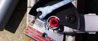
- Secure the hammer with rubber pads to avoid damaging the plastic housing. Clamp the end of the tool with a gas wrench. Use a hammer to push the wrench toward the tool shaft.
The second option is used as a last resort. If after several blows the drill or chisel cannot be removed, stop. You may damage the blow. Disassemble the cartridge and gearbox. Try to knock the equipment out with a blow. After this procedure, you will most likely have to replace the raster sleeve. To avoid this problem later, lubricate the end of the tool.
How to remove a stuck drill from a chuck
How to remove the mode switch
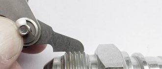
On some models of rotating hammers, the switch is removed, returning to the extreme right position, on others, to the extreme left. Let's consider an extremely correct position.
- Set the mode switch to the clock. If there is no punching mode, use a drill to punch it.
Impact switch
Use a screwdriver to move the switch
Analysis of the electrical part of the hammer drill
- Unscrew and remove the back cover.
- Remove the power cord mounting bolts.
- Remove the buttons and wires from their slots.
READ How to Connect a Screwdriver to Network 220
Analysis of the mechanical part of the hammer drill
- Remove the plastic gear housing. You will see an aluminum housing with a thrust bearing inserted into it, an intermediate shaft, and a raster bushing.
Raster sleeve and drunk bearing
Removing gears
Removing the gear
The raster bushing is removed from the bushing
Sleeve with attacker
Grinders with rear handle
Grinders with a rear handle allow you to get to the brushes in a slightly different, simpler way:
- Near the handle you need to find a small repair window, closed with a plastic plate, which is fixed with a self-tapping screw.
- You need to unscrew the screw, pry the plastic plate into the groove with a screwdriver, remove it from the case, opening the repair window.
- The following steps for replacing brushes are the same as for low-power angle grinders: release the band spring (1), release the plug (2), remove the brush from the guide block by the wire.
- Then insert a new brush, connect the plugs, secure the graphite rod with a ribbon spring, close the repair window with a plastic plate and screw in the self-tapping screw.
- Repeat all steps with the second brush located on the opposite side of the body.
It is quite possible that there may be other ways to replace graphite brushes, depending on the design features of the grinders.