Measuring with a thread gauge
Accurately identifying the threads on a fastener is critical before selecting and installing the correct fittings.
How to measure thread:
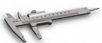
- Use a combination caliper to measure the thread diameter. It is worth taking into account that the threads of the used fitting may wear out and become distorted, so calculations may not be accurate.
- Use a thread gauge to determine the number of threads per inch. For metric connections, the distance between the threads is calculated. To do this, you need to place the device on the thread until it fits snugly, and then compare your measurements with the thread diagram.
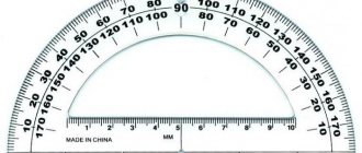
- If the port is located at an angle, determine the angle of inclination using a protractor on the sealing surface. The center line of the fitting and gauge should be parallel.
Using a combination of three tools, identifying connectors is easy. The use of a caliper, thread gauge and protractor allows accurate measurements of most connections.
A caliper is used to measure the diameter of an external internal thread. When comparing calibration measurements to thread diagrams, keep in mind that threads on connections that have been in service may be worn and distorted from use. This results in inaccurate comparisons with thread tables.
For English, British and other European threads, the pitch meter has an inch scale. However, for metric parts, the device will determine the distance between threads in millimeters.
The protractor is used by placing it on the sealing surface. The center line of the fitting end and gauge should be parallel. In English, the thread size system and pitch (number of threads per inch) are specified along with the thread type.
When using a thread gauge, you need to align it with the threads and make sure that it fits snugly. Match the measurement to the thread, then calculate the diameter using a caliper.
Measurements during the design and manufacture of threaded connections
The “bolt-nut” type connection is one of the most common in mechanics. When designing and manufacturing structures, the problem of how to measure a bolt with a caliper is often difficult.
Before starting work, it is worth remembering that the main dimensions of a bolt/nut are the length of the product and the diameter of the thread. A standard bolt of any design does not require such measurements. It’s a different matter when the bolt is made at home, or you need to measure the fastener without dismantling the connection. The following situations are possible here:
- Between the head and the opposite end of the rod there is a plane or part/plate, the dimensions of which do not allow the insertion of the measuring jaws of a caliper. In this case, using the main measuring scale and a depth gauge (sometimes called a “Columbic”), the height of the head, the thickness of the washer (if any), the thickness of the intermediate element and the height of the part protruding from the opposite side of the joint are determined. The obtained result is added up, and then, according to the tables of correspondence between the lengths of the rod and the “turnkey” dimensions that the bolt has, the standard size of the fastener is determined.
Measuring internal threads and imprinting threads
Thread pitch measurement
Measuring thread pitch without a thread gauge
For metric fasteners, thread pitch is used instead of TPI. Distance is also measured in millimeters.
To determine the thread pitch, a caliper is used to calculate the distance from the top of one thread to the next. The formula used for this is M2 x 4 x 5 mm, where M2 refers to the diameter of the bolt (in millimeters), i.e. 4 is the thread pitch in millimeters, which means it is equal to 4 mm between each thread peak, and 5M is bolt length.
Thread pitch is used to measure the threads of a bolt or nut to ensure they fit together. If the threads of the bolt and nut are different, they either do not grip or wear out the threads, resulting in an unusable connection.
Small threaded fasteners have a denser helical structure and are usually less pronounced. A coarse threaded connection has larger and deeper threads. This means that if the threads are slightly damaged, it may still work. Most standard metric fasteners have fine and coarse threads. Each of them can be identified using or thread pitch.
In the US and UK, fasteners typically have thread sizes ranging from ¼ to 20 inches and ¼ to 28 inches. To determine which of these threads is coarse and which is fine, you simply need to take the TPI number (20 and 28) and compare them.
Don't forget that coarse thread means the thread is larger, so smaller ones will be able to fit within an inch. So 20 means it's a coarse thread and 28 means it's a fine thread. TPI and thread pitch will vary depending on the diameter of the fastener, so the value will not always be 20 and 28.
For metric fasteners, similar parameters would be represented as M8 x 1.25 or M8 x 1. For thread pitch, the distance between two points is the second number, meaning the higher the number, the fewer threads. It follows that M8 x 1.25 is a coarse thread, and M8 x 1 is a fine thread.
Measuring threads with a caliper
The first step is to determine whether the threads are tapering. To do this, place the points of the caliper on either side of the object that needs to be measured. Align it to the outside of the threads at the lower end, away from the head. This is how the width is determined.
Next, you need to move the tip so that it touches the threads. The measurement should appear on the screen if the instrument has a display. Otherwise, you will need to rely on the numbers on the sliding part. You should then do the same on the threaded area near the head of the fastener. If the number is higher at the head, then it is a tapered thread.
You can also use a caliper to measure the diameter. If the thread is tapered, measure at the 4th or 5th thread down from the head, i.e. in the middle of the threaded area. If it does not taper, then you can measure anywhere along the thread. When using a caliper, you may notice that there are several places where the arms do not meet closely together, sometimes along the edge of the ruler. There is no need to place what needs to be measured in these spaces.
The numbers should be placed in a standard measurement. Once the pitch value is obtained, you can measure the length of the bolt or screw from under the head and place all the numbers into a standard measurement. It will have the diameter, then the thread pitch and the length. If a metric screw has a diameter of 4 millimeters, a thread pitch of 0.4 mm and a length of 8 mm, then the calculation will be M4 x 0.4 x 8M. For an American screw this could be 1/4" in diameter, 20 TPI and 1" long. The formula will be: 1/4 inch x 20 x 1 inch.
All about reinforcement diameter
Manufacturers of fittings often use worn-out equipment, and the fittings are produced slightly larger than the required diameter.
Manufacturers of fittings often use worn-out equipment, and the fittings are produced slightly larger than the required diameter. According to the tolerances, it passes, and the total tonnage corresponds, but in terms of linear meters there is a shortage. In the search for these meters, time is lost, the project stops and a feeling of deception remains.
When trying to determine the diameter of the reinforcement, it should be taken into account that the cross-sectional shape of the reinforcing bar is more reminiscent of an ellipse than an even circle. Therefore, by measuring a rod in different places, a person gets a series of numbers. In addition, when taking measurements along the body of the rod and along the ribs, the difference in indicators is several millimeters.
This confuses the calculations.
How to determine the diameter of the reinforcement?
The size should be viewed in the accompanying documents. In them, manufacturers indicate the so-called nominal diameter of the reinforcement; it is called the reinforcement number. This indicator indicates the size of the rod from which this piece of reinforcement was made (taking into account some assumptions).
That is, the profile number of the original workpiece is comparable to the nominal diameter of the finished product. As a result, you can do the following (you will need a caliper):
- Measure the body of the rod.
- Measure the diameter of the protruding ribs.
- Sum the indicators and divide the result by 2.
Many people do this. They get an average number that suits everyone.
The non-professional option works at the everyday level, since professionals don’t ask such questions. For such calculations, the following expressions are appropriate: “maximum diameter of reinforcement” and “minimum diameter of reinforcement.”
These are exactly the two indicators that were obtained when measuring the body and edge of the rod.
Using these figures, a table was developed that specifies the minimum and maximum dimensions and what nominal diameter of the reinforcement they correspond to.
Diameter of fittings. Diameter ratio table
| nominal diameter | maximum diameter | minimum diameter |
| 6 mm. | 6.57 mm. | 5.57 mm. |
| 7 mm. | 7.75 mm. | 6.75 mm. |
| 8 mm. | 9 mm. | 7.5 mm. |
| 9 mm. | 10 mm. | 8.5 mm. |
| 10 mm. | 11.3 mm. | 9.3 mm. |
| 12 mm. | 13.5 mm. | 11 mm. |
| 14 mm. | 15.5 mm. | 13 mm. |
Reinforcement weight
When selling reinforcement, the price is indicated per ton of product. When starting a small-scale construction, a person calculates the footage of the rod required for the project.
Any fittings that comply with GOST have fairly accurate weight indicators per 1 linear meter of rod. This data is also included in the table and is actively used at metal depots.
The ratio of minimum, maximum and nominal diameters corresponds to a specific weight indicator. This helps determine the weight of the reinforcement by diameter.
Foundation reinforcement diameter
Having prepared a trench to accommodate the supporting base of the object under construction, it is time to calculate the required diameter of the reinforcement. You can, of course, take a thicker rod and a larger quantity. But this will increase the cost of materials and leave the impression of amateur performance.
It's better to do it according to science
In addition, there is everything necessary for this. And first of all, the table.
| No. of fittings | Number of bars and cross-sectional area | |||||
| 1 PC. | 2 pcs. | 3 pcs. | 4 things. | 5 pieces. | 6 pcs. | |
| 6 | 28.3 mm2 | 57 mm2 | 85 mm2 | 113 mm2 | 141 mm2 | 170 mm2 |
| 8 | 50.3 mm2 | 101 mm2 | 151 mm2 | 201 mm2 | 251 mm2 | 302 mm2 |
| 10 | 78.5 mm2 | 157 mm2 | 236 mm2 | 314 mm2 | 393 mm2 | 471 mm2 |
| 12 | 113.1 mm2 | 226 mm2 | 339 mm2 | 452 mm2 | 565 mm2 | 679 mm2 |
It is necessary to measure the future foundation and calculate its cross-sectional area. If we take the height and width of 600 and 500 mm. The multiplied values will give a result of 300,000 mm2. For such a foundation, the cross-sectional area of the reinforcing bars from the cross-sectional area of the foundation will be 0.1%. That is, 300,000: 100 x 0.1 = 300 mm2. This is the cross-sectional area of all the rods. The nearest readings in the table suggest a value of 302 mm2. Which corresponds to 6 rods No. 8. Transverse reinforcement can be less thick, but not less than 6 mm. It's better to take the same 8 mm. Using tables, you can effectively calculate the parameters of the future foundation and not incur unnecessary costs.
New Product Notifications
I want to receive
Measuring rivets
Rivets are a kind of fasteners consisting of two parts: a head and a mandrel. The cap is the short side that needs to be measured for its length and diameter. The mandrel is the long, thin end that comes off the rivet during the installation process.
First of all, you need to place the head into the round holes on a special rivet gauge. The holes have different diameters into which rivets fit. When they are inserted into the hole, the cap should fit snugly.
If there is a gap, the size is too large for the rivet. In the opposite situation it is too small. Using the selection method, you need to determine which size most accurately reflects the parameters of the fastener.
Next you need to measure the length of the rivet. To do this, you need to attach the cap to the open upper areas. Make sure that the washer or flange of the rivet is pressed well.