Metal ruler
This measuring instrument is perhaps the simplest in its design. With the help of metal rulers, the value of the measured quantity is determined directly.
Metal ruler
It should be noted that these measuring devices are also widely used for marking materials and parts. Modern industry manufactures them with measurement limits of 1000, 500, 300 and 150 millimeters, and either one or two scales are applied to them.
Levels
The horizontal height marking is determined by the water level. It functions on the principle of communicating vessels. It consists of a plastic polymer tube and two volumetric flasks at the edges.
The spirit level allows you to assess the compliance of the horizontal and vertical working surface. Made from wood, aluminum or plastic material. Length - 30 cm-2.5 m. Consists of three windows containing glass tubes that are not completely filled with liquid that is resistant to low temperatures.
Calipers
measuring instrument, widespread and actively used in technology (especially in mechanical engineering), is much more complex than a metal ruler and provides much higher measurement accuracy. A caliper consists of such main parts as a ruler-bar, on the edge of which the main scale with equidistant divisions of 1 millimeter is applied, and a vernier - a reading device with an additional dashed scale.
Calipers
The division price of the verniers of modern calipers is either 0.1 or 0.05 millimeters, and as for the measurement limit, it reaches 2000 millimeters.
Calipers are used to measure both the external and internal dimensions of parts, as well as the depths of holes. In addition, they are used for various marking works.
Shtangenreysmas
Types of measuring instruments
Top 15 best car tool kits: inexpensive and professional options
Now, having an idea of accuracy and errors, let's move on to the instruments themselves.
Let's start with the ruler. Professional rulers are made of spring steel. The scale is applied double on both edges. Moreover, sometimes opposite the centimeter scale, they place a scale in inches.
Sometimes such rulers have a section with 0.5 mm divisions.
Modern steel rulers with 0.5 mm divisions
By connecting two rulers at right angles, we get a square. They can measure the length and mark a 90 degree angle.
There are metalwork, carpentry and construction squares.
The most accurate is a mechanic's square. The marks of his rulers are engraved with a laser; the plates of the rulers are steel, twice as thick as construction material.
Carpenter's squares are made of hard wood, the marks are applied with paint or burned out.
Construction angles differ from the first and second ones in their large sizes (up to 70 cm) allowing for the layout of large rooms.
Angles other than straight angles are measured with a protractor - a semicircular ruler divided by notches into 180 degrees. A protractor with a movable ruler is called a protractor.
Even more often than a ruler, mechanics use a tool called a caliper.
They measure not only the length, but the internal or external diameter of round parts and holes. Some models are equipped with a retractable rod for measuring the depth of grooves and niches.
A caliper measures dimensions much more accurately than a regular ruler.
The caliper is equipped with an additional scale. By matching its marks with the marks of the main scale, we will be able to determine the size of the part being measured with an accuracy of one tenth or five hundredths of a millimeter (see photo).
A micrometer is an order of magnitude more accurate than a caliper. By clamping the part between its retractable rod and the fixed base, we will determine the dimensions with an accuracy of hundredths of a millimeter.
The micrometer has not only a linear, but also a ring scale
Shtangenreysmas
This measuring tool is designed to measure the heights of parts and accurately mark them. The maximum measurement limit of height gauges is 2500 millimeters, and the division price of their verniers is 0.1 or 0.05 millimeters.
In most cases, this measuring tool is used when working on special cast iron plates. It is on them that it is installed along with those parts that need to be measured or marked.
In order to draw a line on the part to be marked using a height gauge, a special replaceable leg is used. The measuring tool itself moves directly along the surface of the slab.
Application of measuring machines
Classification of analog measuring instruments
To make accurate measurements, not only hand-held measuring instruments can be used, but also special machines called coordinate measuring equipment. The peculiarity of this equipment is the ability to take measurements in three coordinates, which ensures maximum accuracy of calculations.
The design of the machines resembles a table on which working heads equipped with sensors are installed. To make a control measurement, the workpiece is placed on the table, and sensors read the parameters of the part.
Machines can capture data in two ways:
- contact, involving the use of a probe sensor;
- contactless, in which reading occurs by sending a light signal to the surface of the part.
Micrometer
A measuring instrument of this type is designed to make fairly accurate measurements of small linear dimensions. The maximum measurement limit of modern micrometers reaches 600 millimeters, and the accuracy is 0.01 millimeters.
Micrometer
Micrometers (as, indeed, all micrometric instruments) are equipped with special reading units based on a screw pair with a thread pitch of 0.5 millimeters. With its help, the longitudinal movement of the measuring screw is converted into circumferential movements made by the drum scale. It is on the basis of the angle of its rotation that the value of the measured size is determined.
Micrometric depth gauge
Micrometric depth gauge
In essence, this measuring instrument is designed exactly the same as a micrometer. The only difference is that it is equipped not with a bracket, but with a base. It is in it that the so-called measuring stem is installed. In order to measure depth using a micrometric depth gauge, a special rod is used. It is installed on a screw and has a special shape. The measurement limit of modern micrometric depth gauges is up to 300 millimeters, and the division price of their verniers is 0.01 millimeters.
Dial indicator
Types and their purpose
Types of tools are divided into:
- manual;
- stationary.
The most common are hand-held sets, which easily fit in special containers-suitcases. Based on popularity, kits are divided into three types of kits:
- universal;
- automobile;
- special.
By universal kits we mean kits that contain devices common for household needs. For example, automotive tools consist mainly of matching wrenches and sockets. Special kits are designed to perform work in certain specialties. Another type of device is a set of measuring instruments that are used by professionals, as well as people who have an idea of how to handle them.
Measuring
Tools of this type are designed to perform work requiring high precision. Typically, such kits are used, for example, by professionals for the manufacture of parts, repair of equipment, installations and mechanisms.
The types of instruments used to make measurements are divided into:
- devices that control production processes;
- for measuring quantities (pressure, temperature, concentration, electric current and its presence);
- mechanisms used for laboratory measurements.
Manual
Unlike automotive kits, hand tools are intended for other types of work. The so-called “gentleman’s sets” consist of:
- pliers. This type of tool is universal. First of all, pliers are suitable for plumbing and electrical repairs and for eliminating minor problems: cutting through a wire, nail, tightening a nut, etc.;
- Screwdriver Set. Of course, you can tighten the self-tapping screw with pliers, but it’s easier to do it with a screwdriver. The same rule applies to screws and screws that have different head formats;
- assembly knife. The household should always have a good assembly knife, with a strong blade, capable of cutting strong fabric, tarpaulin, and also removing insulation;
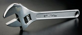
- set of keys, including socket. This list should also include an adjustable wrench, as well as what is popularly called a pipe wrench, where jaws serve as the clamp. Such wrenches will help to carry out repair work on plumbing parts, for example, tighten large nuts, fix a pipe in the desired position;
- sampler This type of measuring device, first of all, helps to determine the presence of electrical voltage and check the operation of electrical appliances.
Power tools
A tool that is designed to perform various jobs is gaining popularity. For example, sawing wood and metal parts, sanding surfaces and similar processes. The most common power tools are:
- drills;
- planers;
- jigsaws;
- screwdrivers;
- electric sharpener;
- grinding machines;
- renovators.
Almost all modern instruments can be purchased in specialized stores. But it is better to buy those kits that are manufactured by well-known companies. Since these manufacturers do not risk producing low-quality products that comply with electrical safety measures.
Dial indicator
This measuring instrument is a device where very small movements made by the measuring probe are converted into angular movements of the arrow. Dial indicators are used when it is necessary to determine with a significant degree of accuracy those deviations that a certain part has in its geometric shape in relation to the specified parameters. In addition, these devices are used to control the relative position of surfaces.
Mechanical goniometer
Thread gauge
This measuring tool is used to accurately determine the thread pitch and profile. Structurally, it is a package of metal templates, each of which exactly repeats the configuration of a particular thread. Thread gauges that are designed to determine the pitch of metric threads are marked M60°, and those measuring devices that are intended to determine the number of threads per inch when measuring inch and cylindrical pipe threads are marked as D55.
Radius meter
Radius meter
This measuring tool is designed for measuring fillets and radii. It is a set of metal templates made in the form of plates from high-quality alloy steel. Moreover, they are all divided into those that are used to measure protrusions and those that are intended to measure depressions.
Gauge blocks
Special devices
There is a well-known measuring device called a protractor.
Its purpose is to measure the angles of parts, and the design consists of the following elements :
- The device itself has a half-disk with a printed measuring scale;
- the ruler has its own movable sector, where the vernier scale is printed;
- The movable sector of the ruler is secured with a locking screw.
The measurement process with such a device is simple. The part is applied with one of its faces to the ruler. It must be moved in such a way that a uniform and sufficient gap is formed between the edges and the rulers. The sector is then secured with a screw. The readings are taken first from the ruler and then from the vernier.
Control and measuring devices have found quite wide application in various areas of production, home life, plumbing and construction work. They differ both in scope and measurement capabilities.
All devices can be divided according to the method of conversion, output of information and type of output information, purpose and other criteria. Having a good classification, you can find a specific tool for certain tasks and operations.
But their main goal is to measure readings, record them and control production processes. It is recommended to use precise measuring devices, however, the device becomes much more complex. This will require taking into account a large number of factors and measuring parameters in order to display accurate readings.
Read also: The hydraulic press does not press
The simplest measuring instruments include a scale ruler, calipers, and bore gauge.
The scale ruler is intended for measuring flat surfaces, as well as for determining dimensions measured with a bore gauge or calipers. Scale rulers are manufactured in different lengths from 100 to 1000 mm. The division value of the scale bar is 0.5 or 1 mm; to facilitate counting, every 5 and 10 mm are marked with elongated strokes. The zero division of most rulers is applied at the left end. When measuring, the ruler is applied to the part being measured so that the zero line exactly coincides with the beginning of the line being measured. In Fig. Figure 13 shows how to measure using a scale bar.
Rice. 13. Techniques for measuring with a scale ruler
Calipers are used to measure the external dimensions of parts. The value measured by the calipers is then determined by placing the calipers on the scale ruler. Calipers, like the simplest bore gauge, are rarely used.
A bore gauge is used to measure the internal dimensions of parts. The measured value is also determined using a scale bar.
Vernier calipers belong to multidimensional sliding measuring instruments (Fig. 14, a). It is intended for measuring external and internal dimensions and markings.
Rice. 14. Vernier calipers (a), examples of measuring the size and reading measurements with an accuracy of 0.1 mm (b, c, d)
A caliper consists of a rod with jaws rigidly attached to it, a frame with jaws moving along the rod, a device for micrometric feed, consisting of a slider, a locking screw, a nut and a screw.
The frame is moved as follows. The engine 6 is secured with a locking screw, and the frame locking screw is released. After this, by rotating the nut, the screw and the frame associated with it are slowly moved. The caliper has a vernier.
Calipers are produced with a measurement accuracy of 0.1; 0.05 and 0.02 mm. The last two have a micrometric feed, allowing you to install the caliper with high precision. The leftmost strokes of the vernier and the rod are called zero and when the jaws are closed they coincide. To determine the size to be measured, with the jaws of the caliper apart, count the whole number of millimeters that the left zero vernier stroke has passed along the rod, and then find the vernier stroke that exactly coincides with any division of the rod scale. The ordinal number of this division determines the fractions of a millimeter that should be added to the whole number of millimeters. When measuring internal dimensions, the thickness of the jaws, which is indicated on them, should be added to the reading made on the main scale and vernier. Examples of readings are shown in Fig. 14, b, c, d.
A depth gauge (Fig. 15, a) is used to measure the depth of holes, grooves on shafts, etc. Measurement with a depth gauge is carried out in the same way as with a caliper.
A vernier gauge (Fig. 15, b) is used to measure the thickness of wheel teeth. A vernier gauge is a combined measuring instrument consisting of two fixed rods that form a single unit and two movable verniers. The vertical vernier is designed to set the height at which the tooth thickness should be measured, and the horizontal vernier is designed to measure the tooth thickness at a given height. The measurement accuracy of the caliper is 0.02 mm.
The micrometer is used to measure the external dimensions of parts with an accuracy of 0.01 mm. The most common are micrometers with the following measurement limits: from 0 to 25 mm, from 25 to 50 mm, from 50 to 75 mm and from 75 to 100 mm.
The micrometer (Fig. 16) has a bracket into which a hardened and ground heel is pressed, a micrometer screw, a stopper, a stem, a drum and a ratchet.
Rice. 15. Vernier depth gauge (a), caliper gauge (b): 1 - locking screw, 2 - slider, 3 - micrometer screw, 4 - nut
Rice. 16. Micrometer
The ratchet is connected to the drum by a ratchet, pressed by a spring, and 50 divisions are marked on the left end of the drum, beveled along the circumference. The micrometer screw has a thread with a pitch of 0.5 mm, therefore, for one revolution of the screw, its end moves by 0.5 mm, and when the drum is turned by one division, the screw moves by 0.01 mm. On the surface of the stem there are divisions with an axial stroke.
Rice. 17. Micrometric bore gauge (a), extension to it (b)
To measure a part, it is placed between the micrometer screw and the heel, after which the drum is turned using a ratchet and the screw is pulled out until it comes into contact with the part. When the screw rests on the part being measured, the ratchet will turn freely, and the screw and drum will stop. To determine the measured size, you need to count the number of millimeters on the stem scale, including the half-millimeter division passed by the reference stroke (0.5), and then look at what number on the beveled part of the drum coincides with the axial stroke of the stem. This number will correspond to hundredths of a millimeter, which must be added to the previous data.
Rice. 18. Micrometric depth gauge
Rice. 19. Squares
A micrometric bore gauge (Fig. 17) is used to determine the internal dimensions of parts with an accuracy of 0.01 mm. A micrometric bore gauge consists of a micrometric screw (Fig. 17, a), a drum, a sleeve with a locking screw, and a tip with a spherical measuring surface. There is also a spherical measuring surface on the right side of the micrometer screw. Dimensions are measured in the same way as when measuring with a micrometer.
The micrometer bore gauge has a set of extensions that extend the measurement range. At one end of the extension there is an internal thread (Fig. 17, b), and at the other end there is an external thread. The end of the extension with internal threads is screwed onto the bore gauge stem, and the end of the extension with external threads is used to screw an additional extension onto it in order to increase the measurement limits.
Rice. 20. Universal protractor of the Semenov system
Rice. 21. Goniometer UG-2
The micrometric depth gauge (Fig. 18) is used to measure blind holes and recesses with an accuracy of 0.01 mm. It consists of a base, a drum, a ratchet, a vernier, a stopper, and a measuring rod. The principle of measuring with a depth gauge and a micrometer is the same.
To measure angles, as well as determine the accuracy of filing planes along the “clearance”, squares and universal protractors are used. Squares (Fig. 19) are usually made of steel.
The UG-1 goniometer (Fig. 20) of the Semenov system is universal, designed for measuring external angles. It consists of a base on which there is a scale from 0 to 120°, rigidly connected to a ruler, a movable ruler, a clamp, a removable square, a vernier and a micrometric feed device.
The UG-2 protractor (Fig. 21) consists of a base, a base ruler, a sector, a square, a removable ruler, clamps and a vernier. This protractor can measure external and internal angles.
On the main scale of protractors, degrees are counted, and on the vernier scale, minutes.
Limit gauges for measuring holes are made in the form of double-sided cylinders (Fig. 22) and are called plug gauges, and for measuring shafts - in the form of one-sided and double-sided staples, called gauge gauges (Fig. 23, a, b). Limit gauges can determine the largest and smallest permissible dimensions of parts.
Read also: Warm electric floor pie
For extreme calibers, one side is called pass-through and the other is called non-pass-through. The through side of the plug gauge is used to measure the smallest hole, and the non-go side is used to measure the largest. With a clamp gauge, on the contrary, the largest shaft size is determined by the go-through side, and the smallest by the non-go-through side. When measuring, the pass side of the gauge must pass freely into the hole or along the shaft under the influence of the weight of the gauge. The non-go side of the gauge should not go into the hole or along the shaft at all. If the non-passing side of the gauge passes, the part is rejected.
Radius templates are used to measure the radii of curvatures of products.
Such templates are made in the form of thin steel plates with convex or concave curves. The templates are stamped with numbers showing the size of the radius of curvature in millimeters.
Probes. To measure the size of the gaps between parts, feelers are used (Fig. 24), which are steel plates of various thicknesses. Each plate indicates its thickness in millimeters.
Thread control is carried out using thread plug gauges, threaded rings and templates.
Thread plug gauges (Fig. 25, a) are used to check the threads of nuts. They are made from tool steel and look like a bolt with a precise thread profile. Checking the thread of the nut is done by screwing it onto the go-through or non-go-through side of the plug gauge.
Threaded rings (Fig. 25, b) are used to check the threads of bolts and represent a nut with an exact thread profile. The bolt thread is checked by screwing it into the threaded ring. One ring is a pass-through gauge and the other is a non-go-through gauge.
The thread gauge (Fig. 26) is designed to check and determine the thread pitch on bolts, nuts and other parts. It is a set of steel plates - threaded templates with tooth profiles corresponding to the profiles of standard metric or inch threads. Thread gauges typically have a set of templates with metric threads on one end and inch threads on the other. Each template is marked with thread dimensions.
Rice. 22. Size control with a double-sided plug gauge
Rice. 23. Double-sided (a) and single-sided (b) staple gauges
Rice. 25. Threaded plugs (a) threaded ring (b)
To check the threads on a bolt or nut, you need to apply the thread gauge templates successively until you find a template whose teeth exactly match the threads of the part without clearance. The measured thread will correspond to the size of this template.
The indicator is designed to measure deviations of dimensions from the specified ones, as well as to detect the ovality and taper of shafts and holes. In the repair business, the dial indicator is most widely used, the structure of which is shown in Fig. 27.
The indicator body contains a mechanism consisting of gears, a rack, a spiral spring, a sleeve, a measuring rod with a tip, a speed indicator, and a scale with an arrow. The large scale of the indicator has 100 divisions, each of which corresponds to 0.01 mm. When the measuring rod moves by 0.01 mm, the arrow will move around the circle by one division of the large scale, and when the rod moves by 1 mm, the arrow will make one revolution. The indicator scale is set to the zero position by rotating it by the rim.
Before measuring the product, the indicator is fixed in the bracket of the universal stand (Fig. 28) so that the tip of the measuring rod touches the surface of the product being measured. Next, behind the rim 5, set the zero division of the scale against the arrow (Fig. 27). After this, the product or indicator is slowly moved. The amount of deviation is determined by the arrow readings on the indicator scale.
Rice. 26. Thread gauge
Rice. 27. Dial indicator: 1 - measuring rod, 2 - sleeve, 3, 10, 11, 13 - gears, 4 - scale, 5 - bezel, 6 - body, 7 - arrow, 8 - speed indicator, 9 - spiral spring, 12 - spring, 14 - measuring tip
Rice. 28. Indicator with a universal stand: 1 — indicator itself, 2 — hinged lever, 3 — stand, 4 — base
Rice. 29 Indicator bore gauge
An indicator bore gauge (Fig. 29) is used to measure the diameters of engine cylinders. A full turn of the indicator needle corresponds to a change in dimension A by 1 mm. Since the scale has 100 divisions, the scale division value is 0.01 mm. The indicator arrow is set to zero by turning the rim. The indicator comes with a set of interchangeable tips that allow you to measure cylinders of various diameters.
Optical measuring instruments. Measuring instruments based on optical measurement principles include optimeters, instrumental microscopes, and various measuring machines.
Pneumatic instruments are used to measure the external and internal surfaces of precision parts, as well as to determine the cleanliness of surface treatment. Pneumatic devices operate on compressed air, which is supplied by a compressor. The advantage of such devices is the simplicity of their design and maintenance.
Electrical measuring instruments make it possible to make measurements with high accuracy. Such devices are based on electrical contact, capacitive and inductive measurement methods.
Measurement errors and their causes. When measuring parts, there is always some difference between the actual size of the part and the size obtained as a result of measurement. The difference between the measured value and the actual value is called error or measurement error.
The main causes of measurement errors are the following: – inaccurate installation of the part being measured or the measuring tool; – errors when taking instrument readings, which occur in cases where observation when taking readings is carried out from the wrong angle of view. It is always necessary to observe in a direction perpendicular to the plane of the scale; – violation of the temperature conditions under which measurements must be made. The state standard for measurement provides a normal temperature of 20 °C. In practice, the part being measured often has a lower temperature than the temperature of the measuring tool; this also leads to errors, since it is known that metals change their dimensions when the temperature changes. When cooled they contract and when heated they expand. When heated by 1 °C over a length of 1 m, metals elongate by the following values (mm): steel - 0.012, cast iron - 0.010, bronze - 0.018, brass - 0.019, aluminum - 0.024; – the surface of the part being measured is dirty or dirty; - measuring tool; – errors of the measuring instrument; violation of the constancy of the measuring force for which the measuring instrument is designed.
Storage and care of measuring instruments. Measuring instruments are stored in dry, warm rooms. Do not store instruments in damp areas or in areas with sudden temperature fluctuations, as this will lead to corrosion of the instruments. Each tool should have its place.
The simplest tools are stored in cabinets, on racks or hung on the walls. Complex instruments, such as micrometers, calipers, gauges, etc., are stored in special cases.
To protect against corrosion, measuring instruments are lubricated with acid-free petroleum jelly or bone oil. For long-term storage, the instrument is wrapped in oiled paper to protect it from contamination and exposure to humid air. Before work, the measuring surfaces of the instrument are washed with gasoline and wiped with a clean rag, and after finishing work they are wiped again, then lubricated and put in their place.
Measuring instruments must be checked regularly using precision test instruments.
“>