How to Remove a Gear from a Electric Screwdriver Motor
The DC motor
is made of a cylinder type, in which permanent magnets are located in a circle inside the housing.
How to remove a gear from a motor, how to repress a screwdriver .
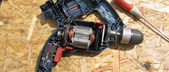
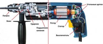
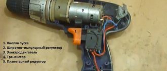
The motor armature is located on support bushings made of brass. The armature itself is made of electrical steel with high magnetic permeability. Windings of insulated copper wire are placed in the grooves of the armature. After an equal number of turns, the winding has access to the collector plates. The drive gear (sun gear) is pressed onto the armature shaft. The motor brushes touch the commutator plates on the tail of the armature. For reliable contact, the brushes are spring-loaded and isolated from the motor housing. According to the screwdriver circuit, voltage is supplied only to the brushes. If you change the polarity of the voltage supplied to the motor brushes, it is not the direction of rotation that will change. Planetary reductor
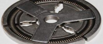
The screwdriver is made in a separate housing. The gearbox includes the following elements: ring gear, sun gear (pressed onto the armature shaft), no satellites. Gearbox parts are made from both plastic and non-metal. For a more complete picture of the operation of the gearbox, it is necessary to clarify the location of the individual parts.
The ring gear is a cylinder, inside of which there are teeth along the entire circumference along which the satellites move during operation. The satellites are installed on the carrier pins. Between the satellites of the first carrier, the engine drive gear (the first sun gear) comes in. How to remove paint from a concrete wall: 4 methods. The first carrier, on the opposite side of the satellites, has a drive gear (the second sun gear), which, when assembled, fits between the satellites of the second carrier.
If the gearbox is two-stage, the second carrier is rigidly connected to the shaft on which the cartridge is attached. Thus, you get a kind of sandwich of two carriers with satellites. This sandwich is located inside the ring gear.
.
The ring gear is rigidly mounted in the housing using protrusions on its end, or, in other words, on the sides. The protrusions rest against protruding balls, spring-loaded by an elastic ring along the entire circumference
.
How to remove
old paint from wood removing paint from. The ring is usually spring-loaded by a load limiting mechanism spring. The spring force can change based on the position of the load regulator.
Design features of angle grinders from domestic manufacturers
Among domestic manufacturers, a special place is occupied by the products of such well-known brands as Interskol, Fiolent, Lepse.
Angle grinder repair Interskol
With proper use, Interskol grinders can work for years.
Along with the infrequent failure of the grinder gearbox, in which the weak link is a pair of gears and a bearing, there have been cases of malfunctions in the stator.
To replace the gears of the gearbox, it is necessary to disassemble the gearbox housing, pos. 19, by releasing the cover, pos. 6.
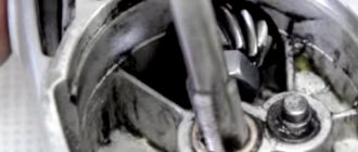
The driven gear pos. 11 is pressed onto the shaft pos. 8 and is removed using a press. The bearing pos.9 is removed with a puller.
You can repair the stator of an Interskol angle grinder yourself if you know the necessary data. When disassembling a burnt stator, you must count the number of turns of the wire used and its cross-section.
Video:
Repair of angle grinder Lepse
Grinders under the Lepse brand are marked with the LPS Lepse Kirov 1.8-230-A. These grinders trace their history back to the famous Soviet-made grinder IZH. An amazingly durable tool with the most vandal-proof design.
The advantages of the Lepse grinder are the ability to replace worn carbon brushes without disassembling the body of the machine.
Repairing Lepse angle grinders in terms of replacing brushes is simple. Through special windows pos. 45, closed with caps pos. 48, carbon brushes pos. 47 are inserted into the brush holder housing pos. 46.
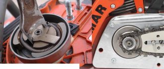
When repairing the gearbox of a Lepse angle grinder, it is necessary to dismantle the gear pair.
The driving small helical gear is mounted on the rotor shaft on a key and secured with a nut.
The driven gear, pos. 15, is screwed onto the spindle shaft, pos. 10, and secured with a nut, pos. 18.
Repair of angle grinder Fiolent
Recently, Fiolent grinders have become especially popular. What attracts us is not only the affordable price, but also the reliability of the tool.
It is recommended to start repairing the Fiolent angle grinder with your own hands by studying emerging faults. If you need to disassemble the Fiolent angle grinder, then in order to remove the driven gear, pos. 11, it must be pressed out from the spindle shaft, pos. 8.
To remove the spindle shaft bearing, you must first remove the large helical gear. These are minor inconveniences.
Replacing the rotor bearings requires the removal of the small helical gear, pos. 22.
How to repress a screwdriver motor gear? The easiest way!
If you want to change the motor on your screwdriver, watch this video, replacing the motor is not difficult
The operation of the gearbox is as follows: the engine sun gear rotates the satellites in a circle around the ring gear, and accordingly the carrier rotates at a lower speed than the engine speed. The first carrier transmits torque through its sun gear to the second trinity of satellites, which also rotate around the ring gear
, which means the speed of the second carrier decreases to a greater extent.
The second carrier, as mentioned above, is connected to the cartridge shaft. This happens in a two-stage gearbox. There are models of screwdrivers with three-stage gearboxes; they have an additional planetary mechanism inserted into the gearbox. Remove the bearing from the armature of electric motor
. At the bottom of the article there is a video showing the operation of a planetary gearbox.
There are models of screwdrivers that do not have a conventional gearbox.
For convenience during the work process, some screwdrivers have two-speed gearboxes. The first speed is intended for tightening screws (0-450 rpm, not increased torque), and the other is for drilling holes (0-1400 rpm).
When rotating the chuck under load, there comes a time when more force is required to complete the work, the last stage of tightening the screw, or when it is necessary to limit the force. The load regulator comes into operation. The adjuster spring force is not enough to hold the ring gear, so the oil does not come off the balls. It turns out that the engine begins to rotate the ring gear, characteristic clicks are heard, and the cartridge stops at the same time. To use a screwdriver while working in drilling mode, the ring gear is blocked and its rotation is prevented.
Speed controller
assembled based on a PWM controller not a key N-channel field-effect transistor. The operation of the regulator is controlled by a variable resistor, the position of which depends on the force of pressing the power button (trigger).
Reversing is reduced only to changing the polarity of the voltage supplied to the motor brushes. For this purpose, you are provided with changeover contacts, which are activated by the reverse lever.
Battery
. To power the screwdriver, a small-sized battery is installed in the housing. The battery for a screwdriver is a set of small elements contained in one housing.
The supply voltage range for different brands of screwdrivers is from nine to eighteen volts. The higher the supply voltage, the more powerful the screwdriver itself.
Video demonstrating the operating principle of a planetary gearbox:
What repairs can a user make to an angle grinder with his own hands?
Although the grinder is not a particularly complex tool, the user cannot perform repair work on all components.
Along with simply replacing the bearings or gears of the gearbox, there are malfunctions that cannot be made without special equipment or devices.
- To press out the driven gear you will need a press. It will not be possible to wind the rotor without tools.
- Such malfunctions include rotor failure. For the average consumer, such a malfunction ends with a trip to the service center.
- Advanced users can revive a burnt out rotor with certain skills and concepts. But sometimes it’s easier to buy a new one than to rewind.
For most users, repairing an angle grinder with your own hands is limited to a certain range of faults.
Systematization of faults in the electrical part of angle grinders
- The simplest fault that causes the angle grinder to not turn on is a broken power cord. Most often, a break occurs in the power cord near the plug or at the entrance to the instrument. The malfunction can be easily resolved by replacing the power cord or removing the broken piece of wire.
- Increased heating in the area where carbon brushes are installed. Most often, such a malfunction occurs due to shortening the carbon brushes below the nominal size. The length of carbon brushes cannot be shorter than 8 mm.
- The grinder's power button goes down. The malfunction is due to burnout of the internal contacts in the button. Eliminated by completely replacing the switch with a new one.
- Some models of angle grinders use a device that allows you to smoothly regulate the speed of the angle grinder. The angle grinder's speed regulator improves the smooth operation of the angle grinder and prevents the working tool from biting. Repair of the angle grinder speed controller consists of completely replacing it.
Grouping of faults according to the mechanical part of the angle grinder
- The appearance of extraneous noise in the grinder gearbox, heating of the gearbox. The malfunction is associated with the destruction of the support bearing, wear of the gear teeth of the gearbox, and drying out of the lubricant. Eliminated by replacing gears when tooth wear is high. If there is slight wear on the gear teeth, you can try to fix it. The tooth profile is corrected manually by filing using a round file and a drill. The lubricant is replaced with a new one every time the gearbox is repaired. New lubricant is applied to thoroughly washed parts.
- Bearing replacement is required when it is damaged or large play appears. In some models, the bearing is mounted on the spindle with interference. Replacement requires special equipment, in particular a press. Parts need to be cooled or heated.
- Replacing the bearings on the rotor is required when large runout occurs. The presence of increased runout can be easily seen on the rotor commutator and by the wear rate of the carbon brushes.
Simple faults and methods for diagnosing and eliminating them yourself
If your grinder does not turn on when you press the “Start” button, then the test begins by inspecting the power cable at the point of entry into the tool.
Unscrew the lid of the angle grinder and check the integrity of the power cord using a tester or phase. Strictly follow safety rules.
If the power cord is intact and the angle grinder does not turn on, replace the “Start” button.
If the grinder does not work when installing a new button, check the quality of fastening of the carbon brushes and their tight fit to the rotor commutator.
Do-it-yourself complex malfunctions and repairs of angle grinders
The following types of breakdowns require certain knowledge and skills to eliminate them:
- Seized or damaged bearings.
- Licking or destruction of gear teeth of the gearbox.
- Open circuit or short circuit in the rotor or stator.
- Failure of control circuit parts.
- Destruction of the gearbox housing.
How to Remove a Gear from a Drill Gearbox
Repairing a drill with your own hands is difficult, or can a home handyman do it?
After a hammer and pliers, a drill is the most popular household tool. The device is used actively and does not break down from time to time.
The cost of repairs will add up to a tidy sum, not to mention buying a new drill. If you understand how a power tool works, you won’t be afraid to disassemble it, and naturally repair it.
Drill device
Regardless of any additional options directly from the manufacturer, the electric drill consists of a standard set of components:
- Network cable. Despite the elementary nature of this unit, 50% of the so-called defects are associated with it. The power cable usually breaks. Common break points are the entry point into the handle, not soldering the contacts of the start button (especially if the switch body has a free play, does not move when the button is pressed)
- Spark suppression capacitor
- Start button. Weak point - after checking the cable, we test the myth element
- Outer winding (stator) of the motor
- Motor rotor support bearing
- Brush units - holders are not actually current-collecting brushes
- Motor rotor contact manifold. The cleanliness of its contacts is the key to uniform rotation
- Drill body
- Motor cooling fan
- Operating mode switch. Based on the model, reverse the gearbox or connect the impact mechanism of a hammer drill. Mechanical or contact drive
- Gearbox housing. Found on every model; the cartridge is not directly attached to the rotor axis
- Reducer gears. If a mass of dust gets in, the lubricant loses its characteristics. The gearbox quickly wears out and does not require replacement
- Chuck bearings. Carry a huge load and require maintenance
- Chuck axis. Hammer drills are equipped with a return spring
- Drill chuck. The collet mechanism can be quick-clamping, in other words, it is made “turnkey”.
Do-it-yourself drill repair begins with checking the functionality of all components.
The working version of disassembling the tool usually does not come to fruition. As annoying as it may sound, it is not such a turn that you need to prepare for.
DIY drill repair - typical electrical faults
To gain access inside, you need to remove half of the case. The upper part is considered to be the part where the heads of the mounting screws are located, not known. At the bottom there will be fixed mechanisms and no wiring.
The electronic circuit of the drill is ordinary and does not require special consideration.
The exception is options with an electric reverse switch and not a speed controller. These nodes are made as separate modules and do not change completely. Therefore, according to the repair theory, there is an option to consider them as a single part.
Network wire
If the drill does not engage at all, in other words, power is lost when the position of the tool changes - this is a contact problem. For you, one of the wires broke inside the rubber sheath. The integrity of the cable is checked by a tester using another circuit from a light bulb with a battery.
And after connecting the tester, you specifically need to tug and not bend the wire to search for a hidden break. After localizing the damage, part of the cable is cut off, the contacts are cut again, and no connection is made.
If a break occurs along the wire, it should be replaced. There is an option to return the break point using soldering, ensuring reliable isolation of the repair site.
How to change gears in a conventional drill The chuck rotates Repairing power tools
VK: Group: Life channel:
How to disassemble an angle grinder and remove bearings. Step by step steps
After disassembling this device, you can replace broken bearings, re-lubricate all parts, dismantle damaged brushes and install new ones.
In order to separate the rotor and stator housings, it is necessary to first remove the handle housing in the machine. This is done so that it is possible to remove the carbon brushes. They hold the rotary manifold.
The second step is to unscrew the four screws that secure both housings - rotor and stator.
Take out the gearbox along with the starter and start disassembling it. There are also screws on the gearbox that need to be removed. There are four of them in total. This procedure will require some effort on your part, since the factory assembly involves the use of sealant.
Grinders of different models have different types of gears. In low-power models, spur gears are used. With a power of more than a thousand watts - the use of helical gears.
Once you remove the gear cover, you will be able to remove the assembly that houses the helical gear. To remove it, use a press or puller.
To do this, you will have to use special thin tubes. For this reason, it will be inconvenient to use the puller.
Before removing the gear, it is necessary to check the play in the gear connection. Also check that all teeth are intact. And the contact patch is checked.
If you have identified the following signs in a bearing that is located on the spindle shaft:
- when you scroll it, a characteristic noise is heard;
- noticed the appearance of backlash;
- no lubrication.
If all these signs are present, it is necessary to replace the old part with a new one. To do this, the bearing must be removed. How to do it?
First of all, remove the gear along with the retaining ring. After this, you can easily remove the worn element. When you remove the rotor shaft assembly, the bearing may remain in the gearbox, inside the housing. In this case, use a hammer with a soft tip on top.
READ How to connect a capacitor in an angle grinder
To remove the drive gear in an angle grinder, do the following:
- clamp the rotor, unscrew the nut with an open-end wrench;
- the washer is removed;
- Now take out the gear itself.
After checking the appearance of the gear, decide whether this part needs to be replaced. Keep in mind that both gears need to be changed at the same time.
Low-power angle grinders are equipped with a needle bearing, which serves as a support bearing.
Dismantle this part only when it is completely destroyed. There is a proven way to remove a destroyed clip.
1.Choose a tap diameter larger than the inner diameter of the cage.
2.Place and secure it into the screwdriver chuck. Gradually, at low speeds, tighten it into the cage. When the tap hits the housing bottom in the gearbox, the cage will rise.
The rotor shaft has two more bearings, in addition to needle bearings. To remove them from the rotor, I would recommend using a puller.
The bearing attached to the manifold to remove . The impeller is also equipped with a bearing, which will take a little more time and skill to remove. Both bearings are covered for protection with special rubber caps.
To remove and replace these parts, the nuts are unscrewed, the spur gear , as well as the plastic protection. You can now freely remove the bearing from the rotor shaft using a puller.
If you don't have a puller in your tool kit, there is one method, take note of it. Remove the bearing with a vice along with two metal strips and a hammer with a special metal attachment.
How to remove a pulley from an electric motor: choosing the appropriate method
A universal technique, the use of which most often justifies itself, is a simple mechanical effect - light blows from opposite sides of the pulley, alternately. Thus, the pulley gradually moves from its seat on the shaft and can be removed.
In more complex cases, the list of necessary actions is planned based on the following factors:
- method of attaching the pulley to the motor shaft (type of landing);
- the condition of the surfaces at the junction (depending on the service life and the susceptibility of the materials to corrosion).
Under what conditions is it possible to remove a pulley from an electric motor without a puller?
There are a number of cases when, to effectively solve the question of how to remove a pulley from an electric motor, you cannot do without a puller. However, there is usually no need to use special devices if:
- the pulley was installed without pressing, that is, the diameter of the shaft does not exceed the diameter of the pulley hole;
- the mating surfaces were not subject to deformation during engine operation.
On low-power electric motors, reliable fixation of the pulleys is ensured by means of a splined fit, threaded connections or locking elements (rings, washers). To separate the pulley from the engine in such cases, it is enough to unscrew the nuts (or remove the rings). The situation is more complicated if a ring with jagged edges is used at the attachment point.
Before unscrewing the connecting elements, it is recommended to carefully secure the pulley using a vice. To avoid deformation of the pulley, wooden spacers are installed between the vise plates and the surface of the clamped part.
How to remove a bearing from an LG washing machine drum
Household appliances from a well-known Korean manufacturer are highly reliable, but some parts and consumables require periodic replacement or maintenance. To remove the washing machine yourself, you must first disconnect all communications, drain the remaining water, and disassemble the washing machine to remove the drum.
READ Reasons why the grinder stopped working
Then the fixing bolts are unscrewed and the assembly is divided into two parts. Using improvised means or special devices, the bearings are knocked out, the seats are completely cleaned, and all parts are checked for damage and deformation.
Installation of new elements and reassembly is carried out in the reverse order.
Interskol
Some designs of bearing units are made without the use of interference fits. So, for example, in the following video, the ball bearing of the gear housing cover of the Interskol model is assembled into a support structure using a washer secured with threaded connections. For a better fit to the plane of the body, the surface of the washer is coated with an adhesive composition.
Heating method
If a thermal method was used to install the pulley, based on the expansion of materials, metals in particular, when heated, then a thermal effect on the pulley will be required for its dismantling:
- due to the heating produced from the edges of the pulley, the diameter of the hole increases by fractions of a millimeter and, accordingly, the degree of pressing against the shaft decreases;
- after this, it becomes possible to move the part from its seat by successively tapping it from different ends.
What you should pay attention to when using this technique:
- one-time heating may not be enough, especially with a large pulley hole diameter;
- the shaft must be reliably isolated from the temperature-increasing action that is applied to the pulley, since in the case of indirect heating of the shaft, the mating of the elements will only become stronger;
- if this happens, you must wait until the elements have cooled completely and repeat the procedure.
Depending on what material the pulley and shaft are made of, another strategy may be chosen, in which, on the contrary, the shaft is cooled.
Using a puller to remove a pulley
Before removing the pulley from the electric motor shaft, you can install a special device - a puller, the device of which is simple. The design includes:
- a metal plate with a hole in the center and narrow slits;
- a nut welded to the plate;
- bolts (the size of one, with a recess in the end, must correspond to the welded nut, the other two - smaller).
The disadvantage of this method is the need to slightly damage the integrity of the pulley, in the surface of which for attaching the puller:
- 2 holes are drilled;
- the thread is cut (to the size of the small bolts of the puller).
The puller operates as follows:
- the plate is attached with two bolts to the pulley;
- the third bolt begins to be screwed into the central nut, while its end rests against a metal ball, previously fixed in the centering groove of the shaft;
- As it is screwed in, the bolt presses the puller plate away from the shaft, gradually removing the pulley from its seat.
Replacing the motor bearing
For home use, exotic instruments are not needed. If external and internal pullers, induction heaters, and special devices for driving are produced for cars, in everyday life everything is simple and straightforward. But it is a mistake to think that there are no difficulties. On the contrary, car service manuals are easy to find, but information on Philips food processor engines is not available. We run into difficulty - we need to disassemble the device without damaging numerous plastic parts.
Sections of the site:
- Pool (1)
- Gazebos (4)
- Landscape design (5)
- Garden and vegetable garden (4)
- Pond construction (1)
- House and cottage (89)
- Water supply (12)
- Entrance to the house (3)
- Country house (4)
- Home sauna (3)
- Chimney (4)
- Fence (2)
- Sewerage, septic tanks (6)
- Frame houses (6)
- Roofing (8)
- Stairs (5)
- Attic (4)
- Modular houses (2)
- Basement (4)
- Siding (7)
- Terrace and veranda (2)
- Smart home (1)
- Foundation (8)
- Engineering systems (4)
- Alternative energy sources (1)
- Drainage system (1)
- Boiler rooms (1)
- Tools and equipment (21)
- Furniture (7)
- Real estate (4)
- News (2)
- Arrangement and comfort (36)
- Office renovation (5)
- Repair and decoration (139)
- Balconies and loggias (9)
- Bathroom (5)
- Doors (7)
- Children's room (4)
- Windows and glazing (15)
- Tile (8)
- Floors (18)
- Ceilings (11)
- Repair Tips (19)
- Walls (24)
- Electrical (18)
- Countries and travel (8)
- Construction calculators (2)
- Construction materials (22)
- Services (7)
READ How to Disassemble a Bosch Grinder
How to disassemble a household appliance containing an electric motor
Numerous food processors and blenders are designed specifically in such a way that they cannot be disassembled. This provides warranty workshops with a stable income - and they already pay companies for service manuals and a license. So the owners are scratching their heads about how to replace the bearing.
Motor rotor U – 8830
Now we will describe the process of replacing the bearing in the electric motor of a Philips food processor, model U - 8830. You will find that modifications of this motor are widely used in blenders, meat grinders and other appliances. The differences mainly concern the shaft. In the case under consideration, a bevel gear is mounted on one side, and on the opposite side there is a drive for knives with limited rotation. When the electric motor U-8830 is removed, we begin. Do not rush to unscrew the screws, it is still to no avail. Let's consider the design of the electric motor U - 8830:
- Both ends of the shaft are occupied by drive gears, narrow gray and conical in shape and white, wide, in the shape of a wheel.
- A coupling is used on the collector side. Let's call it a friction bearing.
- The brushes are held by plates where the contacts are soldered. The varistor leg is bent from the side, from the outside (we don’t know why this is needed; what’s wrong with the common soldering area).
The bearing is hidden in the frame
From the manifold, the wide drive wheel sits on a left-hand thread. To remove, grab the end of the long gray electric motor shaft gear in a vice. Then start rotating the wheel counterclockwise as viewed from the commutator side. Carefully! The nut is brass and comes off easily.
Wide drive wheel
Now we get rid of the long gray gear. Easier to do with a bearing puller. You need to pry the threads with the grips, then slightly pull them towards you. The part is simply removed. It is acceptable to try using a small plumbing wrench (see photo). They found that his lips fit between the frame and the thickening of the gear. You will need to set the grip width with the nut and carefully grasp the thread at the base. Do not squeeze too hard to avoid damaging the plastic.
Carefully begin to twist the gear counterclockwise and clockwise while removing it from the shaft. After a while, the gap between the frame will increase, then the part will fall off the shaft of the electric motor. Partial success.
When the ends of the shaft are freed, let's move on to the brushes. Brass occupies a middle place in terms of bending strength between aluminum and copper, we act carefully. Using a slotted screwdriver, bend the clamps and remove the contact pads. The springs and brushes come out reluctantly; you can help by inserting a sharp object into the side. Now it's time to untwist the frame into two parts. The friction bearing easily moves out of position; the opposite half remains on the shaft, into which the rolling bearing is pressed.
Replacing a bearing on an electric motor shaft
We believe that a standard tool (puller) is suitable for removal. If there is nothing similar, you will have to use the method recommended by motorists (see photo):
- Take a standard adjustable wrench of a decent size so that it fits freely into the gap between the frame and the shaft.
- The lip is fixed. The end of the shaft is placed on the board, then the bearing is knocked down with light blows.
The authors did not have an adjustable wrench suitable for the procedure. I found one on the farm that was too large; the lips fit too tightly to the stator windings of the electric motor, stripping off the varnish insulation. Without thinking twice, we found a block of low-strength concrete. Then, using the legs of a gas plumbing wrench, they grabbed the frame with the bearing, as shown in the photo, placed a piece of board on top of the shaft, and made several blows. It is possible not to lay the piece of wood from the indicated end; there is no thread on the edge, but only a chamfer along the fixing ring.
The bearing is tightly pressed into the frame. As can be seen from the photographs, it is covered with a lid, which during the dismantling process managed to be slightly deformed and is now barely held on by four rivets. The element can definitely be removed and thrown away (or mounted with new rivets). The electric motor shaft bearing is knocked out of the groove in an accessible way; it is permissible to use a standard puller. Try using thick round wood. The bearing on our electric motor is normal; the listed procedures do not yet threaten it.
Please note that the niche for pressing is too large. Its height exceeds the width of the bearing. We believe this is due to the multi-purpose purpose of the U-8830 electric motor. We believe that the readers have already hammered the bearing into place, it’s time to put everything together. We push a little Litol under the balls and scroll a couple of times. If the test of the electric motor bearing went well, we put the cap on the rivets, or leave it and try to put it on the shaft.
Seizing the shaft with a wrench
The method shown in the photo is suitable. The handles of the gas plumbing wrench are placed on the above-mentioned brick, forming a grip. The shaft on the collector side is equipped with a left-hand thread, which is protected with a block of wood (not shown in the photo). A few blows and the part will fall into place, but! The shaft on the bearing side does not have a limiting chamfer; it is easy to push it all the way and damage the varnish insulation of the rotor winding of the electric motor, requiring replacement or rewinding.
To avoid this, place a piece of soft rubber in the right place. Hard (for rugs) is fundamentally unsuitable. Or control the driving depth in your own way. If we find too much, we take up the gas key again and repeat the procedure for dismantling the electric motor frame, but not completely, but by a couple of millimeters. Having achieved success, we begin assembling the shaft. We recommend assembling the frame first, then attaching the brushes, and putting on the wheel with left-hand thread. The last to be mounted is a narrow gray bevel gear.
We remind you that it is pressed onto the shaft of the electric motor, and the clamping ring was not initially included in our kit. At this point we consider the assembly complete. Finally, let's point out the reason for using a closing plate: without it, you will have to use sophisticated means to adjust the position of the bed. The bearing sits tighter on the shaft than in its niche; when you try to slightly increase the distance to the collector coils, it begins to slip out. It's difficult to set the correct distance. For this reason, we recommend monitoring the process of reassembling the electric motor so that you do not have to adjust the position for a long time.
Putting the bearing frame in place
Typical mistakes made when replacing electric motor bearings
If the frame needs to be removed not to replace the bearing, but to rewind the rotor, it is strongly recommended to use the thinnest possible grip that rests on the plate. The legs of the gas plumbing wrench are too thick. It was impossible to get close to the shaft; the stator winding with varnish insulation was in the way. For this reason, the plate was bent. Note that such methods are classified as barbaric. We strongly recommend watching the promotional video about the EKF tool, where professional techniques are demonstrated.
As a result of the demonstration repair, a barely noticeable play appeared on the shaft (as happened in the video with the “bad” master), and when the speed decreased, the bearing began to make a noticeable rustling noise, which is considered a sign of increased gaps between the rolling surfaces. It turns out that the bearings in the electric motor of the juicer must be changed extremely carefully, otherwise the noisy unit will work much worse.
Today in advertising of professional tools we see the same background. This line of thinking already suggests that replacing the bearings of a washing machine electric motor is the job of professionals. As the bearing is replaced, the performance also deteriorates.
Design features of foreign angle grinder manufacturers
In this chapter, we will look at the design features of angle grinders produced under the Bosch, Hitachi and Makita brands, as well as do-it-yourself angle grinder repairs.
Bosch angle grinder repair
Bosch grinders are a reliable tool that does not cause much trouble to the user. But not every user treats the tool correctly. Bosch angle grinder repair most often involves replacing bearings.
Structurally, all Bosch angle grinders are made according to the same design. The spindle shaft pos. 25 is pressed into the driven helical gear pos. 26 and rests in the gear housing pos. 821 on the needle bearing pos. 51.
When a bearing is destroyed, a bearing race remains inside the housing, which is not easy to obtain. We recommend two methods for removing the needle bearing race. They are described in the section “How to remove a needle bearing”.
If the teeth of a pair of gears are worn out or licked, both must be replaced and only in pairs. When dismantling the gears, remember that the drive gear is attached to the rotor shaft on a thread, and the LEFT gear is secured with a nut. The driven large helical gear, pos. 26, is pressed onto the spindle shaft, pos. 25.
Hitachi angle grinder repair
Hitachi grinders have gained particular popularity among Russian consumers. And this is natural. There are practically no handicraft fakes of Hitachi angle grinders on the market. The simplicity of the design makes it easy to carry out repairs of any complexity.
Grinders from Hitachi are highly reliable and rarely come to the attention of repairmen. The main reason why a Hinachi angle grinder needs to be repaired is a gearbox failure, namely, the wear of gear teeth.
The grinder gearbox is easy to disassemble. To disconnect the gearbox housing, pos. 3, from the stator housing, pos. 37, the carbon brushes must be released.
Unscrew the four screws, item 1, securing the gearbox housing and stator housing. Separate the gearbox housing and the stator housing. The gearbox housing will be disconnected together with the rotor, pos. 8.
To remove the gearbox cover pos. 23, you need to unscrew the four screws pos. 24. The driven helical gear pos. 33 is fixed on the spindle shaft pos. 26 using a key pos. 25 and is driven off with a puller. Bearing pos. 21 is removed with a puller.
Makita angle grinder repair
A special feature of the Makita family of angle grinders is the quick-release protective cover pos. 19.
Makita grinders are more likely than others to be repaired. But the reason is the high percentage of counterfeits that have flooded the Russian market.
A true Makita is a reliable, durable tool. But, like all angle grinders, it suffers from failure of the gearbox and its gears.
Reducer gears are replaced if they become jammed or destroyed.
To repair a Makita 9069 or Makita 9558 HN angle grinder, you need to disassemble the angle grinder.
If the gearbox is faulty, and this is determined by the appearance of play in the spindle shaft, jamming of the gearbox, or slipping of the driven gear, then the gearbox should be disconnected from the stator housing. Release the carbon brushes, pos. 35, unscrew the four screws, pos. 10, and disconnect the gear housing from the stator housing, pos. 37.
At the next stage, unscrew the four screws pos. 18 holding the rotor cover pos. 15. The driven gear pos. 14 is removed using a tool. The drive gear, pos. 43, is secured by a keyed connection and secured with a nut, pos. 42. The rotor shaft bearings pos. 3 are removed using pullers.
How to fit a bearing onto a shaft using an induction heater
This is the case when the magnetic core is specially made solid, and then the alternating voltage is turned on. Due to eddy currents, the metal becomes very hot. The magnetic circuit shows the shape of the gate, where the top bar can be easily removed from its place. This is where the bearing goes. Eddy currents and the magnetization reversal effect quickly take their toll. In a matter of minutes, the bearing heats up to the required 111 degrees and slides onto the shaft on its own. Just press down a little on top. By the way, the video demonstrates that when heated by oil, it is easy to destroy the upper race of the bearing with blows from a sledgehammer. We take your word for it.
We hope that now replacing the fan motor bearing will not scare readers. Expensive equipment goes to a service center, cheap equipment comes to us. If beating occurs, it is easy to buy a new electric motor at any time for training in professional skills.
The best skill is to learn from other people's mistakes. They were specifically allowed in the experiment to show readers: Russia’s barbaric methods are not always suitable for imported equipment. Please note: not every workshop owns professional tools. Carry electric motors and bearings in the correct place.
How to remove an anchor from an angle grinder?
Often, during operation, power tools become clogged with small mechanical debris. This is fraught with overheating and failure of the device. To prevent such situations, it is recommended to periodically disassemble the tool to assess wear and clean it from contaminants.
The grinder also needs regular preventive examination. When sawing or grinding various hard materials with it, fine mechanical dust flies in different directions.
It often gets directly inside the instrument. To clean the device, you will have to disassemble it, and you will need to navigate the question of how to remove the anchor from the angle grinder.
Similar manipulations are also performed during the process of repairing or replacing any part of the tool.
In an angle grinder, it is the anchor that is most susceptible to natural wear. Due to overheating or regular use, a short circuit may occur in its contacts. You can also remove the anchor from the angle grinder to check its serviceability.
In most cases, a failed part is not suitable for further use. It is replaced with a new one.
But how to disassemble the tool without breaking it, and how to remove the anchor of an angle grinder? In this article we will try to provide you with detailed information that will help you understand all the intricacies of the process.
How to remove an anchor from an angle grinder - preparation for work
Disassembling a tool, as a rule, does not require special training. It is enough to be attentive and careful, and you will be able to correctly remove the anchor from the angle grinder. The surface on which the power tool is disassembled must be level, dry and clean. Make sure there is sufficient lighting so that all parts and fasteners are clearly visible.
The process of removing an anchor from an angle grinder
Every serious work requires close attention. When disassembling the tool and removing the anchor from the angle grinder, you must try to remember the location of the components inside the body in order to successfully perform subsequent assembly. For bolts, take a separate place so as not to lose parts. When disassembling the device, you may find the following tools useful:
- screwdrivers;
- pliers;
- hammer;
- vice;
- gas key.
You may also need some lubricant and a rag. All parts of the equipment are in close contact with each other. This is necessary so that under load they do not vibrate or break, hitting each other.
Sometimes such dense placement can cause difficulty in disassembly, including removing the anchor from the angle grinder. But just be extremely careful and attentive, and you will succeed.
Analysis of the elements, components and systems of the device involves disassembling the gearbox, since they form a single whole.
How to remove an anchor from an angle grinder - step by step guide
The process is carried out in several stages:
- In order to remove the anchor on an angle grinder, you must first unscrew the bolt that holds the casing . You can easily perform this manipulation, since there are no tight connections. To carry out the work you will need a universal multifunctional screwdriver with a ratcheting mechanism.
- After unscrewing the bolt, the outer casing moves towards the cable . Some models of grinders are created using a variety of components. A part that is present in all power tools is the motor. It consists of a stator, armature, commutator and brushes. After removing the body, you need to remove these same brushes. To remove it, you must first move the springs, after which they can be easily removed.
- Once you have removed the brushes, you can begin to remove the rotor . To do this, you need to unscrew the four outer bolts. You can unscrew them using a screwdriver. Then the rotor head is removed. It is quite easy to remove it - manually, pulling it up. All that remains is to remove the rotor. It is removed along with the plastic pillow. This action can also be performed manually.
- After removing the anchor from the angle grinder, you need to remove the rubber seals on its axis . Next, it remains to free the part from the plastic cushion with the bearing and gear. The upper nut is clamped with a gas wrench and unscrewed. This action does not require much effort. After this, the plastic pad, gear and bearing are removed. The anchor has been removed from the angle grinder. Therefore, the process is completed.
To assemble the power tool, all steps must be repeated in reverse order.
Mandatory manipulations when removing the anchor from an angle grinder
Damage may not be visible on contaminated parts. When performing manipulations to remove the anchor from the angle grinder, as well as other components of the tool, do not forget to thoroughly clean them and wipe them with a dry cloth.
If all the spare parts are intact and working, still removing dirt from their surfaces will be an excellent preventive measure to increase the service life of the device.
Perform this step periodically to reduce stress on tool parts when working in challenging environments.
When removing the anchor from the angle grinder and generally disassembling it for cleaning or repair, check the need to replace the lubricant of the metal parts of the tool. Litol-24 lubricant is usually used.
By promptly replacing the lubricant and removing internal mechanical blockages, you can significantly extend the life of your electric angle grinder.
This simple process will help prevent premature wear of the component parts and the tool as a whole, as well as improve its performance.
The main difficulties that may arise in the process of removing the anchor from the angle grinder
Remember the sequence of actions when disassembling the tool and the position of all parts in the body. Sometimes, when removing the anchor from an angle grinder, certain difficulties may arise:
- it happens that bolts and connections rust or threads break off during disassembly;
- as a result of a short circuit, the plastic parts of the device may melt;
- deformed plastic elements stick to metal parts, making disassembling the tool much more difficult.
If you are not confident in your abilities, it is better not to open an angle grinder at home. In this case, you will need the help of a specialist to properly remove the anchor from the tool.
If, when analyzing the condition of the systems, tool parts and removing the anchor from the angle grinder, you find a breakdown that you cannot fix on your own, stop all further actions to restore the operation of the device. Contact a service center or workshop for assistance.
A qualified specialist will conduct a detailed diagnosis of all parts and mechanisms of the tool, will be able to correctly remove the anchor from the angle grinder, and will find and repair the breakdown. Your device will be ready for use again.
Buy the necessary accessories to remove the anchor from an angle grinder from a reliable supplier
To repair the device yourself, you will need a certain tool. High-quality components, as well as devices for removing the anchor from an angle grinder and restoring the functionality of the device, are presented in a huge assortment in the ToolParts store.
Our managers are always happy to provide information support to customers and help in choosing parts. Ordered goods, including devices that will allow you to remove the anchor from an angle grinder at home, are promptly delivered to all settlements of Ukraine.
Source: https://toolparts.com.ua/novosti/kak-sniat-iakor-s-bolgarki