Reasons for replacement
The bearing fixes the position of the shaft, ensuring its uniform rotation. These small parts take on the entire load.
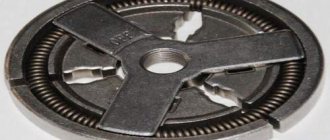
If you are wondering how to remove a bearing from a washing machine, then you suspect that it has become unusable. The reason for this could be a damaged oil seal, which, having lost its tightness, began to leak water. The lubricant was washed out, which led to corrosion and wear of the bearing.
Most users download SMA based on the “as much as it will fit” principle. This is wrong, because over time, overload leads to wear of parts, including bearings. You can notice this by the characteristic grinding sound. It can be heard when spinning or when turning the drum by hand.
Another sign of a bearing problem is leaking. If you find that water is accumulating under the bottom of your washer, it’s time to check.
Untimely replacement can lead to damage to the tank by the drum, wear of the cross and shaft. And this already threatens a major overhaul, which will require installing a new tank and drum.
How to properly prepare for work
First you need to drain the remaining water from the washing machine, as you will need to completely disassemble it. Proceed sequentially:
- De-energize the SM by removing the plug from the socket.
- After disconnecting all communications and shutting off the water supply, drain the remaining water from the intake hose.
- Do the same with the drain filter. It is located under the front panel, behind a small hatch or plinth panel. Open the panel by releasing the latches with a screwdriver, unscrew the filter, and drain the water.
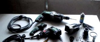
Move the machine away from the wall as far as possible. Now prepare a tool to remove the washing machine bearings. You will need:
- a set of slotted and Phillips screwdrivers, possibly hexagonal;
- a set of wrenches and socket wrenches;
- pliers;
- puller;
- hammer and chisel;
- bolt;
- sealant;
- hacksaw for metal.
Before purchasing a puller, make sure the bearing needs replacement. Then purchase a universal puller suitable for dismantling elements of any size.
Buy a new part. This can be a wheel bearing or any other that is suitable for your model. You can find out the exact numbers and markings after you remove the bearing from the washing machine.
Self-disassembly
Having completed the preparation, you can begin disassembling the SMA. Whatever brand your car is, the repair principle remains the same.
Top and front panel
In some washing machines, it is not necessary to remove the front panel to remove the tank. But we will describe the most difficult disassembly:
- Using a Phillips or hex screwdriver, remove the two bolts on the back of the top cover. Push it forward and remove it from the body.
- Move to the front. You need to pull out the dispenser tray, which is used to pour in the powder. Press the latch in the center and at the same time pull the tray towards you.
- Remove the screws securing the control panel.
- Using a flathead screwdriver, pry open the plastic latches.
- Without unfastening the wiring from the control unit, place the panel on top of the housing. If you decide to put it aside, first take a photo of the location of the connectors and then disconnect it.
- Open the hatch door. Bend the edge of the sealing rubber - behind it there is a clamp. Pry it with a screwdriver and pull it out of place.
- Unscrew the two bolts securing the UBL (lock) of the hatch. Reaching behind the body, disconnect the lock wiring. Tuck the cuff inside the tank.
- Unscrew the bolts around the perimeter of the front panel and remove it.
Now you need to eliminate everything that will prevent you from removing the tank. If your model has a heating element in the front, disconnect its wiring. Mark the location of the wires with a marker or take a photo.
Read also: Connection diagram for an AC synchronous motor
Also remove the front tank counterweights by unscrewing the bolts.
Rear case
To remove the back panel, unscrew the screws around the perimeter. Set the panel aside. You have access to details.
- First remove the drive belt. It's not difficult: pull the belt towards you with one hand, and turn the pulley with the other.
- Secure the drum pulley wheel with a piece of wood to prevent it from moving. Unscrew the central bolt. Carefully pulling the pulley towards you, remove it from the shaft.
- Unfasten the wiring from the electric motor and heating element, if it is located at the rear.
- Unscrew the bolts holding the motor and pull it out of the housing.
Electrical faults
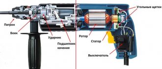
We will begin the description of common breakdowns with the electrical and switching parts. The electrical compartment of almost every drill is located in the handle, where the button is located. To gain access to it, most often you have to completely disassemble the drill. This is not difficult, but it may be difficult to snap the case off: in addition to several screws, it is held in place by clamps. Having halved the case, remember the location of the elements and wiring, or better yet, take a photo, because the layout can be very intricate.
The main sign of an electrical malfunction is that the drill simply does not turn on. Try to move the power cord with the button pressed in the place where it comes out of the housing: a fracture of the core in this place causes 90% of all malfunctions; if it occurs, the drill will show signs of life. You can also determine a power failure by dialing.
Another common cause of breakdown is failure of the reverse button or switch. Try ringing the contacts to which the wires are connected to check for commutation. A faulty button can be replaced, or you can try to repair it. By unscrewing a couple of small bolts that hold the case together, you will gain access to the insides. Assess the condition of the lamellas (they may wear off or oxidize), check the serviceability of the ejection mechanism, the cleanliness of the printed circuit board and the presence of burns on the main contacts.
Malfunctions of a small printed circuit board or potentiometer inside a button, which acts as a speed controller, cannot be treated independently. In such cases, the drill either does not turn on at all, with the contact group fully operational, or operates at a constant speed. The button will have to be changed.
Don’t forget to also check the reliability of the crimping of the terminals, the integrity of the insulation, and the presence of oxides on the contacts. The electrical circuit of the drill is extremely simple; the main thing is to remember the order in which the wires are connected.
Read also: How to connect an Internet cable
How to remove a bearing from a washing machine drum - instructions
Loosen the drain pipe clamp and disconnect it from the tank.
All that remains is to unscrew the bolts of the shock absorbers, which may be located at the very bottom of the body.
Upper parts
Remove the upper counterweight by unscrewing the bolts.
Now you need to remove the powder receiver cuvette. Lift it up and disconnect the pipe by loosening the clamp with pliers. Unscrew the bolts securing the fill valve to the SMA body. Disconnect the wires from it. Remove the cuvette along with the valve.
Disconnect the pressure switch hose attached to the tank. If nothing else is in the way, lift the tank off the hooks and pull it out through the front or top of the CM housing.
Inspection and dismantling
Before removing the bearing from the hub, you need to remove the drum.
If you have a collapsible tank, simply unscrew the screws around the perimeter and remove the top part.
If the tank is soldered, you will have to cut it. For this:
- Mark the locations for future screws around the perimeter. Make holes for them, so you can additionally fasten the halves of the tank.
- With the tank on its side, start cutting from the part that is convenient for you.
Hit the bushing several times with a hammer to push the drum out of the tank section.
Now you will learn how to remove a bearing from a washing machine drum shaft without a puller:
- Place a chisel on the outer ring.
- Tap it with a hammer and try to remove the bearing.
- If it doesn't come out, spray it with WD-40 and wait a while.
To somehow knock out or remove the inner race of a washing machine bearing, you can use the same method, only aimed not at the outer ring, but at the inner ring of the part. This method can be used if the part cannot be removed using a conventional puller.
However, this raises another question: how to remove the remaining outer race of the bearing? You can also knock it out or try to pry it off with a puller.
After dismantling, clean the seat - you've done the job. If the part was faulty, install a new one in place. Lubricate the sawn drum with sealant along the edges and connect the two parts. Secure it with self-tapping screws.
Now you know how to knock out and remove a bearing from a washing machine drum - you can put this knowledge into practice. A video on the topic will help you:
(No ratings yet)
DIY bearing puller
When repairing electric motors, in addition to open-end wrenches and a set of heads, you definitely need to have in your arsenal several pullers for tightening bearings.
Pullers for removing pulleys.
One universal one simply won’t do. If you have electric motors from 1 kW to 100 kW on your site, then you need to have 2-3.
I have in my arsenal two pullers for removing bearings. At the moment, there is a large selection of pullers on the markets, and you can purchase them. But if you have the material, a lathe, gas and electric welding, and the desire, then you can make a puller yourself. And I assure you, it will serve you for decades.
See:
It is imperative to use three-jaw pullers: they are the most comfortable. I will also indicate the dimensions of my own pullers, which have long been tested during repairs. Let's start with a small one, with which you can remove bearings from sizes 202 to 308, large 317 and more. We will need sheet metal 10 mm wide and
Homemade pullers for removing bearings.
round metal 30 mm (for a huge one - 15 mm metal and round timber with a diameter of 50 mm).
First we make a sketch (pattern) of the puller legs. We make the length of the legs 200 mm (at the end of the article in PDF format I will post patterns of the legs of the small and large pullers). Next, we draw a sketch on the sheet metal according to the pattern. You need to cut the legs with a gas cutter (propane and oxygen). After cutting, we process the workpieces using large sandpaper.
Read also: How to melt aluminum
We evenly adjust the sizes of the 3 legs to the same size. There is no need to achieve very perfect dimensions; a difference of 1 mm will not play a negative role in the design. When the paws are made and adjusted, in the upper part we drill two holes (for a small expansion of capabilities) with a diameter of 8 or 10 mm bolts (for a huge 12 or 14 mm 3 holes) for attaching the paw to the core of the puller. We do the same with the remaining 2 legs. We drill holes in them along the first leg, using it as a template. Here you need to try to prevent the discrepancy in size from allowing the bearing to be removed to be captured immediately. Here's a quick overview of how to make puller legs.
Removing bearings without a puller
The usual and effective method for removing a bearing
from the shaft
without a puller
.
See:
Festool ts 55 ebq how to remove the bearing from the armature without a puller
remove the bearings
from the generator armature
without a puller
in five minutes.
Puller in disassembled form.
The next detail is the core. For the core for a small puller, we will need round metal with a diameter of 30 mm and a length of 35 mm (for a large one, 50x45 mm, respectively). In the workpiece, we drill a hole for a 16 mm thread (for a large puller, there is a hole in its workpiece with a diameter of 30 mm) and cut the thread, preferably with a fine pitch. In the prepared part for the core we apply markings, three marks at 120 degrees. And to these places we electric weld two to the marks of the paw holder (the distance between the holders should be as thick as the paw). I think there is no need to describe in detail how to prepare them, since there is no need to adhere to any strict rules and sizes. After welding, we process this part using coarse sandpaper. Now, having tried on the paw, we drill holes in the holders. The holes must be drilled at a distance from the center, so that the installed foot has good movement to the side to capture larger bearings.
And the third part of our puller is the screw. For the first puller we make it 350 mm long, the thread length is 280 mm, for the second - 500 mm long, for the thread 420 mm. Next, we process the workpieces on a lathe and cut the threads. In the upper part of the screw, where there is no thread, we drill through holes with a slight offset in height and perpendicular to each other. These are holes for mounting or a knob. Diameter is at your discretion. The beginning of the screw can be narrowed in diameter by a small distance. I don't describe the details. Everything can be seen in the photographs.
We made these pullers with a mechanic more than 12 years ago . All these years I have had no problems with removing bearings and coupling halves. And most importantly, the quality turned out to be from Soviet times. This necessary tool can be easily made with your own hands.
A bearing is a small element of technical equipment of a car. It requires replacement at a certain interval, and all repair work is carried out according to regulations, otherwise it will be difficult to decide how to remove the bearing and replace it on time. When making repairs yourself, you can encounter a lot of difficulties, thinking not only how to remove the bearing, but also first unscrew this or that nut. There are cases when the fastenings do not give in, and you have to use force or additional leverage. But in everything you need to have moderation, not to damage parts that will be difficult to find later, and to adapt them to a car of a certain brand.
Replacing the drill chuck
Finally, the most trivial problem: the drill turns in the chuck, the degree of clamping has become very low. And not everyone has an idea of how to remove the cartridge for replacement.
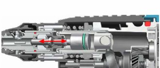
Let's start with the most complex specimens: in drills with a power of over 600–800 W, the chuck may have a wedge-cone fit. The spindle is made of a sleeve into which the shank of the collet chuck is inserted. To remove it, you need to find a hole on the side of the bushing, insert a powerful screwdriver into it and pry the end of the shank, pushing it out. If there is no hole, the bushing is clamped in a vice, and the cartridge is struck lightly with a hammer through a wooden block. In this case, the blows alternate at diametrically opposite points on four sides.
In low-power drills, the spindle has an external right-hand thread at the end, onto which the chuck is screwed, and a hole in the center with a left-hand thread, into which the shunt bolt is screwed. This bolt has a head for a square or Phillips screwdriver; it must be unscrewed. Then, blocking the engine impeller with a nail, try to rip off the cartridge counterclockwise with a sharp but moderate movement. If the thread boils, the drill will have to be disassembled in order to clamp the spindle along with the driven gear in a vice.
Why do you need to change bearings?
- Maximum or average bearing wear;
- Finding an element under prolonged pressure during aggressive driving;
- Impaired balancing of the chassis system, so an urgent decision is made on how to remove the bearing and replace it with a new one;
- The appearance of atypical sounds, creaks when the car is moving, impacts of the cardan on the lower body of the vehicle;
- Detection of wheel play will also force the driver to think about how to remove the bearing from the shaft, carefully install new parts in their seats and return safe maneuverability to the car;
Bearing replacement
The main purpose of the bearing is to reduce friction and protect mechanisms from rapid wear. There is a wide variety of bearings. They differ in purpose, size and location. The part is subject to wear and therefore requires timely replacement. But in solving the problem of how to remove a wheel bearing, a lot of difficulties arise, so experienced craftsmen and amateurs have come up with reliable ways to remove the bearing. Let's look at some of them.
Read also: Types of corrugated sheeting for roofing brands
Bearing sizes and manufacturers
Before replacing a bearing with a new standard product, you need to buy it. The marking of these standard consumables is complex; the numbers in it are deciphered using special tables. Moreover, bearing designations according to GOST 3189 do not coincide with the markings of foreign manufacturers, so the user needs to know the following nuances:
- the marking consists of three parts (main, left, right), and blocks inside them;
- in the left and main parts the blocks are located from right to left, and in the right block on the contrary, from left to right;
- in cars, the front bearing of the generator most often has the designation of the main part 302 or 303, and the rear bearing 202 or 203;
- usually radial ball modifications with code 0 (0302 or 0202) or angular contact balls with code 6 (6303 and 6203) are used;
- therefore, for the specified parameters, you can decipher the dimensions using the table below;
- For foreign-made bearings, similar markings are used.
The suffix (right side of the marking) of imported bearings contains additional information. For example, letters and numbers can represent:
- 2RS and RS – double-sided and single-sided rubber seals, respectively;
- N and NR – groove on the outer ring without a latch and with a latch, respectively;
- J – steel holder;
- Z – sheet protection on one side without seals.
The main problem for a car enthusiast when doing self-repair is the variety of bearing sizes inside the generator:
- it is difficult to guess the markings before disassembling, when the car is still running;
- after dismantling and disassembling the generator, the dimensions and markings are known to the owner, but he has to go to the store in a different car;
- in some stores, sellers practice a convenient system - the car owner takes 4 bearings 202, 203, 302 and 303, and returns two of them back.
Method one, how to dismantle the bearing
There are a large number of special devices that, even at the factory, received a single purpose - to quickly dismantle the bearing, without requiring power investments and financial costs from the auto mechanic or the car owner. Using special tools to remove the bearing from the shaft is an excellent and easiest solution to carry out repairs. You can save yourself from unforeseen situations. And to do this you just need to follow the instructions. Typically, a standard puller is a threaded shaft that is screwed onto special auxiliary holders. They act as fasteners. Using such a simple puller, the bearing is fixed and removed. Everything ingenious is simple!
Bearing puller
Stages of working with the puller
- We take a puller and bring it to the worn bearing.
- We clamp the bearing with a puller.
- We begin with moderate rotational movements to “pull” the bearing from its seat. Remember that movements should be progressive, without much pressure, so as not to damage the elements of a coherent system.
Thus, the question of how to remove the wheel bearing in car services is resolved. The use of special tools and auxiliary equipment makes the work easier, reduces the cost and speeds up the repair process.
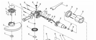
How to remove the rotor from an angle grinder gearbox, step-by-step guide, necessary tools, video
To remove the rotor, commonly available metalworking tools and accessories : hammers, screwdrivers, wrenches, pullers, brushes with soft bristles, wipes for wiping parts, and others. The procedure for performing the operation is the same for all models ; differences arise due to the design of individual components and parts. It is performed as follows :
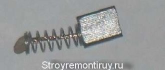
- brushes are removed from the holder cages in order to maintain their integrity;
- the gearbox is separated from the electrical casing body;
- the gearbox cover is removed;
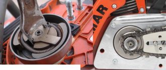
- the nut is unscrewed or the retaining ring is removed, which secures the small drive gear on the rotor shaft;
- the anchor is removed together with the gear and bearing (options without bearing and gear are possible);
- bearings are removed with a puller if there is large play and replacement is necessary;
- All parts and components are wiped with a soft bristle brush and napkins.
The following video shows a complete disassembly of a Bosch model angle grinder . It just shows the general disassembly procedure without detailing individual operations.
a detailed repair of a Makita model grinder with replacement of a failed rotor in the following video. The rotor defect is clearly visible upon visual inspection. In the Makita angle grinder model, removing the rotor and assembling the angle grinder after replacing it is technologically simple without the use of special devices.
In the next video, the spindle jammed on a DVT model grinder . The cause of the defect is that the rotor bearing located in the gearbox housing has crumbled. When removing the rotor from the gearbox, the drive gear is released by unscrewing the fixing nut. The author uses specific examples to show what consequences working on faulty bearing supports can lead to for the rotor and other parts of the angle grinder.
In the review of the Sparky model grinder in the following video, a complete disassembly of all the components of the angle grinder . The author, who has extensive experience in repairing angle grinders of various models, gives brief characteristics of the design features of some assembly units and parts. This marks the easy removal of the grinder rotor from the gearbox housing by hand .
However, not in all models it is possible to remove the rotor from the gearbox without problems . In the following video, using an Interskol model grinder, some users perform this operation with targeted damage to some parts, for example, the impeller. The author describes another option without compromising the design of the grinder's details , based on knowledge of the laws of physics. The difference in the inertial properties of elements with different masses is the basis of the method described in the video. The heavier rotor, using the force of inertia, comes out of the seat of the lower bearing race.
Repair of an electric appliance model grinder is described by the author in the following video. Here, the cause of brush wear was faulty rotor bearings . To replace them, the rotor was removed from the grinder . The removal process from the gearbox is not included in the video. The author claims in the comments that he pressed the bearing out of the gearbox . However, for designs where the bearing is fixed in the support using plates screwed to the gearbox housing, this method is not suitable. Here we apply the method described earlier using the inertial properties of massive parts or by making a technological hole in the impeller through which the fixing plate fasteners are unscrewed.
The following video describes the repair of the gearbox with the replacement of worn gears , for which it is necessary to remove the rotor. This operation is performed using a hammer (necessarily wooden or rubber!). By lightly striking the gearbox housing, is pressed out . Important: if the fit is tight, it is possible to damage some parts of the bearing housing.
Method two, how to dismantle a bearing using heat
Apply the effective laws of physics associated with heating metal. After all, it is 100% known that metal expands at high temperatures, so there is a possibility that the bearing will jump out of its seat on its own, and there will be no need to use physical force, which is sometimes destructive to the entire system.
Tool for mounting and dismounting bearings
Important to remember! If you use this method for the first time, you may not calculate the temperature conditions or your hand will tremble, and as a result, scale may appear along the edge of the nest. And now it will block the path of the bearing. It is recommended to knock off the scale first, only then continue using the second method.
The third way to remove the bearing
If it is not possible to use the first method when deciding how to remove the bearing with a puller, then use the third method. It will require skill and the use of force and auxiliary tools. What is the procedure for action?
- Study the features of the procedure, how to remove a bearing, evaluate your capabilities and level of skills.
- Select the necessary tools: a sledgehammer with a soft tip, wooden stands, a vice.
- Fix the removable shaft in a vice and use a hammer and wooden blocks to knock the shaft out in the opposite direction. Be careful not to damage the entire structure of the part with an awkward blow, because it can be used in the future.
Thus, the third method is used if the bearing is completely worn out and does not come out of its seat, so force must be applied. There are times when it is difficult to solve the problem of how to remove the rear bearings from the shaft, so you simply have to cut them out. This radical method is resorted to by experienced craftsmen who have received a completely worn-out chassis system for repair, and there is no other way to get a bearing to replace it. Beginners are not recommended to use the third method, because they simply will not cope and can damage other elements of the chassis system. In this case, a simple bearing replacement will cost a pretty penny.
Yan-4ik Blog DIY separator puller
Basic methods of pressing a bearing out of a blind hole
METHOD 1. “Displacement”
Prepare the main surface for repair, fix it in a vice and carefully fill the blind hole where the bearing is located with solid oil to capacity. Then gently hit with a hammer - and the bearing race should come out of its seat
In the first minutes, it may seem that the replacement part does not want to give in, but with diligence and caution you will achieve the expected result.
METHOD 2. “Removing the covered bearing”
We use oil. It should leak under the bearing base. We create internal pressure with hammer blows, and the bearing should be pushed out. Try to be careful not to damage the socket.
METHOD 3. “Force”
Sometimes you have to forcefully drag a bearing if it is firmly seated in the socket and does not give in, but on the contrary, somehow “sags”. It will have to be partially destroyed. To do this, you will need a small chisel, which you will use to separate the balls of a small part into two groups. Insert bolts of suitable diameter into the freed space. Then the “jewelry” begins - sawing off the caps, so that the structure is not damaged, and the cap fits in and takes the place of the ball. Then we turn the metal “gimlet” almost ninety degrees. The main task of the manipulation is to ensure that the head catches on the groove in which the bearing balls roll. In the end, the master’s task is to apply force and pull the “turnip” out of the planting nest. Of course, the third method is energy-consuming and a little destructive, but still, it is often used.
METHOD 4 “Using a tool”
Those who are thinking about how to knock out a bearing, not for the first time, and are already tired of difficulties and unforeseen circumstances, have long ago purchased special pullers for bearings. It is also sometimes called collet.
Which way is better
There is no definite answer, because every repair is a special case. It all depends on the age of the car, the wisdom of the vehicle owner, and his responsibility for the technical condition of the car. If a person bought a car to ride and then sell the “tortured steel horse”, then the auto mechanic will have to work on such a car for quite a long time, almost all components of the system will be worn out. In this case, the second or third option is suitable. Ideal car repairs are carried out in a short time and do not require additional financial investments. The first method - the most professional and effective - is used by a car mechanic and will very quickly return the car to operation.
Thus, we have outlined three main ways to remove a bearing, but each craftsman chooses the most optimal one, that is, the one that is most suitable in a particular case. Good luck to everyone with their DIY repairs. If you are not sure, then contact a specialist.
>