Converting Charging a Screwdriver to a Lithium Battery
Probably the owners of screwdrivers want to recycle their batteries into lithium battery cells.
Many articles have been written on this topic and in real material I would like to summarize the information on this topic. First, let's look at the reasons for the usefulness of converting a screwdriver to lithium batteries and against it. We will also look at some aspects of the process of changing batteries. First of all, you should think, do I need this alteration? This will be an outright “self-made” and in a number of different cases leads to wear and tear of both the battery and the screwdriver itself. Therefore, it is necessary to consider what our client can do, the pros and cons of this procedure. You, that after which some of you will decide to give up converting a Ni─Cd battery for a screwdriver to lithium elements.
- The energy density of lithium-ion parts is significantly higher than that of nickel-cadmium parts, which are used by default in screwdrivers. In other words, a lithium battery has less weight than a cadmium battery with the same capacity and output voltage;
- Charging of lithium battery parts occurs much faster than for which the Ni─Cd design is intended. It will take about an hour to charge them safely;
- Lithium-ion batteries do not have a “memory effect”. This means that they do not have to be completely discharged in advance before being charged .
Now about the shortcomings and difficulties of lithium batteries.
- Lithium battery cells cannot be charged above 4.3.5 volts and discharged below 2.7.7 volts. In real terms, this interval is even narrower. If you go beyond these limits, the battery can be damaged. Therefore, in addition to the lithium cans themselves, you will need to connect and install a charge-discharge controller in the screwdriver ;
- The voltage of the Li─Ion element is 3.6─3.7 volts, for Ni─Cd and Ni─MH this value is 1.4.5 volts. In other words, there are problems with assembling a battery for screwdrivers with a voltage rating of 12 volts. From three lithium cans connected alternately, you can assemble a battery with a nominal value of 11.1 volts. Out of four ─ 14.8, out of 5 ─ 18.5 volts, etc. Moreover, the voltage limits during charge-discharge will also be different. In other words, there are difficulties in compatibility of a converted battery with a screwdriver;
- For the most part, standard 18650 cans are used as lithium parts for conversion. They differ in size from Ni─Cd and Ni─MH cans. Today, you will need a place for the charge-discharge controller and wires. All this will need to fit into a standard screwdriver battery case. It will be very awkward for them to work differently;
- A charger for cadmium batteries may not be suitable for charging the battery after it has been rebuilt. It may be necessary to refine the memory or introduce universal chargers ;
- Lithium batteries lose their functionality at low temperatures. This is critical for those who use a screwdriver outdoors;
- The cost of lithium batteries is higher than cadmium ones.
It is necessary to decide on the number of parts in the battery, which ultimately decides the voltage value. For three parts the ceiling will be 12.6, for four ─ 16.8 volts.
We are talking about converting widely used batteries with a nominal value of 14.4 volts. It is best to choose 4 elements, since during operation the voltage will drop quite quickly to 14.8.
A difference of a few volts will not affect the screwdriver's workplace.
THE CHEAPEST CONDITION OF THE CHARGER FOR Lithium Ion Batteries
Already today, a lot of lithium parts will give a huge capacity. And this means more working time for the screwdriver.
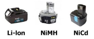
Lithium 18650 battery cells
The nominal voltage of the lithium parts is 3.6-3.7 volts, and the bulk capacity is 2000-3000 mAh. If the battery case allows, you can take not 4, but 8 parts. Connect them two at a time into 4 parallel assemblies, and finally connect them one by one. And therefore you can easily increase the battery capacity. But it’s far from being possible to pack 8 cans of 18650 into a case.
And the last preliminary step is choosing a controller. Its features must correspond to the rated voltage and discharge current. In other words, if you decide to assemble a 14.4 volt battery, then choose a controller with this voltage. The operating discharge current is usually selected to be half the maximum permissible current.
Charge-discharge controller board
Above, we established that the maximum permissible short-term discharge current for lithium parts is 25-30 amperes. This means that the charge-discharge controller must be designed for 12-15 amperes. Then the protection will operate when the current increases to 25-30 amperes. Don't forget also about the dimensions of the protection board. It, together with the elements, will need to fit into the battery housing of the screwdriver.
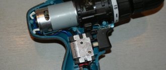
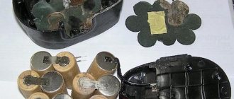
And then comes the assembly process. First, disassemble the battery case. If this is a 14.4 volt model, then inside there will be 12 nickel-cadmium batteries with a nominal value of 1.3.5 volts.
Assembly of nickel-cadmium batteries
Subsequently, it is necessary to solder the purchased elements into an assembly with alternate connections. Then the controller is soldered to it according to its circuit. In this case, balancing points are connected. They have a special connector on the board, and often the wires with the connector are supplied included.
We are remaking the Interskol 12V screwdriver charger for Li Ion batteries
Screwdriver battery housing
After assembling the battery, the plus and minus leads are soldered, and the entire structure is placed in the case. By and large, the process in this case is over. Difficulties only happen with the charger.
However, almost always standard chargers for screwdrivers charge lithium cells easily. With all this, the charge of the cans goes through the controller, so nothing special will happen to the elements themselves.
You can find tips online for saving money on the controller board. In other words, buy a cheaper model designed for the lowest current. And so that it does not limit the operation of the screwdriver, the discharge is done not through the controller, but directly from the cans. And their charging, as expected, goes through the controller.
Source: https://vdiweb.ru/peredelka-zarjadki-shurupoverta-na-litievyj/
Disassembly and assembly
Converting a screwdriver to lithium batteries includes the following steps:
- You should open the old battery by unscrewing five screws.
- Remove the Ni-Mh battery from the housing. It will be noticeable that the contact pad that engages with the contact group of the screwdriver is welded to the negative contact of one of the Ni-Mh cells. Weld points should be cut using a tool fitted with a DREMEL 4000 cutting stone.
- Wires are soldered to the contacts, the cross-section of which is approximately two mm two for the power terminals, not 0.3.2 mm two for the thermistor. The contact pad is glued into the battery case using hot-melt adhesive.
- Based on the internal resistance indicator, four cells are selected on the meter. Many owners of screwdrivers want to convert to 14.4 volts, then the screwdriver is 14.4v to. The value must be made the same for all four devices.
- Lithium cells are glued together with hot glue so that they are compactly located in the housing.
- Welding of cells is carried out on a resistance welding machine using a nickel welding tape (its cross-section must be 2X10 mm).
Charging For Lithium Batteries Screwdriver With Your Hands
Charger for a screwdriver - how to choose and whether you can make it yourself
Screwdrivers are found in everyone where simple repairs are made. Any electrical appliance requires stationary electricity, or in other words, a power supply. Since cordless screwdrivers are very necessary, an additional charger is required.
It comes complete with a drill, so no electrical appliance can fail. So that you do not encounter the problem of non-working equipment, we will study the general description of chargers for a screwdriver.
Analog with built-in power supply
Their popularity is justified by their low price. If a drill (screwdriver) is not designed for professional use, the duration of work is not the first issue. Benefits of automation. Do-it-yourself automated ice drill from a screwdriver has a number of advantages. The task of a conventional charger is to obtain a constant voltage with a current load sufficient to charge the battery.
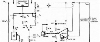
This type of charging works following the principle of an ordinary stabilizer. For example, let's look at the circuit of a charger for a 9-11 volt battery. The type of batteries does not matter.
You can assemble such a power supply (aka charger) with your own hands. It is natural to solder the circuit on a universal circuit board. To dissipate the heat of the stabilizer chip, a copper radiator with an area of 20 cm² is sufficient.
The input transformer (Tr1) reduces the 220 volt AC voltage to 20 volts. The power of the transformer is calculated based on the current and voltage at the output of the charger. Next, the alternating current is rectified using the diode bridge VD1. Typically, the Russian automotive industry (especially the Chinese) use an assembly of Schottky diodes.
After rectification, the current will pulsate, which is detrimental to the production performance of the circuit. The ripples are smoothed out by a filtering electrolytic capacitor (C1).
The role of the stabilizer is performed by the KR142EN microcircuit, or “crank” in amateur radio slang. To obtain a voltage of 12 volts, the microcircuit index must be 8B. The control is assembled on a transistor (VT2) not trimming resistors.
https://www.youtube.com/watch?v=_0WXmu0Q5gU
Automation is not provided on similar devices; the battery charging time is determined by the user. To control the charge, a lightweight circuit has been assembled using a transistor (VT1) and a diode (VD2). When the charging voltage is reached, the indicator (LED HL1) goes out.
More advanced systems include a switch that turns off the voltage at the end of the charge in the form of an electronic key.
Included with economy class screwdrivers (manufactured in the Middle Kingdom), there are no more ordinary chargers. It’s not surprising that the failure rate is quite high. The owner faces the prospect of being left with a relatively new, inoperable screwdriver.
Using the attached diagram, you can assemble a charger for a screwdriver without the help of others, which will last longer than the factory one. Technology for laying paving slabs step by step planning. At this stage, you should decide on the future site for laying paving slabs with your own hands and create a plan for it.
By changing the transformer not the stabilizer, you can easily select the desired value for your battery.
Analog with external power supply
The charger circuit itself is primitive, given the ability. The kit includes a mains power supply, not actually a charger, in a housing that holds the battery module.
It is stupid to consider the power supply, its circuit is standard - a transformer, a diode bridge, a capacitor filter, not a rectifier. The output is 18 volts, for traditional 14 volt batteries.
Do-it-yourself conversion of standard interskol charging for Li-ion-18650
save on your purchases start saving here.
How to charge a li-ion battery using a screwdriver
DO NOT IN ANY CASE INCREASE A SCORET HERE is a link to a conventional converter Here is a slightly different one
The charge control board occupies the area of a matchbox:
You, there is no heat sink on such assemblies, just a high-power load resistor. Therefore, such devices often become unusable. The question arises: how to charge a screwdriver without a charger ?
The solution is simple for a person who knows how to hold a soldering iron.
- The first condition is the presence of a power source. If the “native” unit is working, it is enough to assemble a simple control circuit. If the entire set fails, you can use a laptop power supply. The output is the required 18 volts. The power of such a source is enough for any set of batteries
- The second condition is basic skills in assembling electrical circuits. The parts are the most affordable, you can remove them from old household appliances, or buy them on the radio market for literally pennies.
Schematic diagram of the control unit:
The input is a zener diode of 18 volts. The control circuit is based on the KT817 transistor; amplification is provided by the powerful KT818 transistor. DIY paths for the garden and dacha: 50 photos of how. It must be equipped with a radiator. Depending on the charging current, it can dissipate up to 10 W, so a radiator with an area of 30-40 cm² will be required.
It is the savings on matches that make Chinese chargers so unreliable. A 1 KOhm trimmer is needed to accurately set the charge current.
The 4.7 ohm resistor at the output of the circuit should also dissipate enough heat. Power not less than 5 W. A selection of circuits for homemade chargers for do-it-yourself car batteries.
The LED indicator will notify you that the charge is complete and will go off.
The assembled circuit can be easily placed in the standard charging case. It is not necessary to remove the transistor heatsink; the main thing is to ensure air circulation inside the case.
The savings lie in the fact that the power supply from the laptop is still used for its intended purpose.
For a household screwdriver this is not a problem. I left it to charge overnight before starting work - it was enough to assemble the cabinet. The average charging time for a Chinese cordless drill is 3-5 hours.
Pulse
Let's move on to heavy weapons. Professional screwdrivers are used intensively, and downtime due to a low battery is unacceptable. We leave out the price issue; any serious equipment is expensive. Moreover, the kit usually includes two batteries. While one is in work, the second is being recharged.
A switching power supply, complete with an intelligent charge control circuit, fills the battery 100% in literally 1 hour. You can also assemble an analog charger with the same power. But its weight and dimensions will be comparable to a screwdriver.
Pulse chargers do not have all these disadvantages. Compact size, high charge currents, thoughtful protection. There is only one problem: the complexity of the scheme, and as a result, the high price. However, it is possible to assemble such a device. Saving at least 2 times.
We offer an option for “advanced” nickel-cadmium batteries equipped with a third signal contact.
The circuit is assembled on the popular MAX713 controller. Steps to take when replacing the power supply for a 12V and 18V screwdriver with your own hands. You can find a suitable power source in the market or from someone you know. The proposed implementation is designed for an input voltage of 25 volts DC. It is not difficult to assemble such a power supply, so we omit its circuit diagram.
The charger is intelligent. After checking the voltage level, the accelerated discharge mode starts (to prevent the memory effect). Charging occurs in 1-1.15 hours. A special feature of the circuit is the ability to select the charging voltage and battery type. The description in the figure indicates the position of the jumpers and the value of resistor R19 for changing modes.
If the branded charger
If a professional screwdriver fails, you can save on repairs by assembling the circuit yourself.
Power supply for a screwdriver - diagram and assembly procedure
Many people are familiar with the situation: the screwdriver is alive and well, but the battery pack has died. There are many ways to restore a battery, but not everyone likes to tinker with toxic elements.
How to use an electrical appliance
The answer is simple: connect an external power supply. If you have a typical Chinese device with 14.4 volt batteries, you can use a car battery (convenient for working in the garage). Or you can choose a transformer with an output of 15-17 volts and assemble a full-fledged power supply.
The set of parts is the most inexpensive. Rectifier (diode bridge) and thermostat to protect against overheating. The remaining elements have a service task - indicating input and output voltage. No stabilizer required - your screwdriver's electric motor is not as demanding as the battery.
If your screwdriver batteries are completely out of order, then you can convert it to mains power, see how to make such a power supply in this video
Here you can download the printed circuit board in lay format
This is what the charger conversion circuit looks like.
Source: https://ctln.ru/zarjadka-dlja-litievyh-akkumuljatorov-shurupoverta/
Converting a screwdriver battery to lithium batteries
The industry has been making screwdrivers for a long time, and many people have older models with nickel-cadmium and nickel-metal hydride batteries. Converting a screwdriver to lithium will improve the performance characteristics of the device without buying a new tool. Now many companies offer services for converting screwdriver batteries, but you can do it yourself.
Conversion to 18650 lithium batteries
Nickel-cadmium batteries have a low price, withstand many charging cycles, and are not afraid of low temperatures. But the battery capacity will decrease if you charge it before it is completely discharged (memory effect).
Lithium-ion batteries have the following advantages:
- high capacity, which will ensure longer operating time of the screwdriver;
- smaller size and weight;
- Retains charge well when not in use.
But a lithium battery for a screwdriver does not withstand full discharge well, so factory tools on such batteries are equipped with additional circuit boards that protect the battery from overheating, short circuit, and overcharging to avoid explosion or complete discharge.
You can simply order such batteries on Aliexpress: Find out the price on Aliexpress
When the microcircuit is installed directly into the battery, the circuit opens if the unused battery is located separately from the tool.
Difficulties in reworking
Li-Ion batteries have objective disadvantages, such as poor performance at low temperatures.
In addition, when converting a screwdriver to 18650 lithium batteries, you may encounter a number of difficulties:
- The 18650 standard means that the diameter of one battery cell is 18 mm with a length of 65 mm. These dimensions do not coincide with the dimensions of the nickel-cadmium or nickel-metal hydride elements previously installed in the screwdriver. Replacing batteries will require placing them in a standard battery case, plus installing a protective microcircuit and connecting wires;
- The output voltage of lithium cells is 3.6 V, and for nickel-cadmium cells it is 1.2 V. Let’s say the nominal voltage of an old battery is 12 V. Such a voltage cannot be provided when connecting Li-Ion cells in series. The scope of voltage fluctuations during charge-discharge cycles of an ion battery also changes. Accordingly, converted batteries may not be compatible with the screwdriver;
- Ion batteries differ in the specifics of their operation. They do not withstand overcharge voltages greater than 4.2 V and discharge voltages less than 2.7 V until they fail. Therefore, when the battery is rebuilt, a protective board must be installed in the screwdriver;
- The existing charger may not be able to be used for a screwdriver with a Li-Ion battery. You will also need to remake it or purchase another one.
Important! If a drill or screwdriver is cheap and not of very high quality, then it is better not to remodel it. This may cost more than the cost of the tool itself.
Battery selection
12 V batteries are often used for screwdrivers. Factors to consider when choosing a Li-Ion battery for a screwdriver:
- Such instruments use elements with high discharge current values;
- In many cases, the capacity of the element is inversely related to the discharge current, so you cannot select it based on capacity alone. The main indicator is current. The value of the operating current of the screwdriver can be found in the tool passport. Usually it is from 15 to 30-40 A;
- When replacing a screwdriver battery with a Li-Ion 18650, it is not recommended to use cells with different capacity values;
- Sometimes there are tips to use a lithium battery from an old laptop. This is absolutely unacceptable. They are designed for a much lower discharge current and have unsuitable technical characteristics;
- The number of elements is calculated based on the approximate ratio - 1 Li-Ion to 3 Ni-Cd. For a 12-volt battery, you will need to replace 10 old cans with 3 new ones. The voltage level will be slightly reduced, but if 4 elements are installed, the increased voltage will shorten the life of the motor.
Important! Before assembly, it is necessary to fully charge all elements for equalization.
Disassembling the battery case
The case is often assembled using self-tapping screws, other options are assembled using latches or glue. The glued block is the most difficult to disassemble; you have to use a special hammer with a plastic head so as not to damage parts of the body. Everything from inside is removed. You can reuse only the contact plates or the entire terminal assembly for connecting to a tool or charger.
Battery Cell Connection
Li - Ion batteries for a screwdriver connected in several ways:
- The use of special cassettes. The method is fast, but the contacts have a high transition resistance and can quickly be destroyed by relatively high currents;
- Soldering. A method suitable for those who know how to solder, since you need to have certain skills. Soldering must be done quickly, because the solder cools quickly, and prolonged heating can damage the battery;
- Spot welding. Is the preferred method. Not everyone has a welding machine; such services can be provided by specialists.
Connecting elements by soldering
Important! The elements must be connected in series, then the battery voltage is added, but the capacity does not change.
https://www.youtube.com/watch?v=xggZ7HRHHBU
At the second stage, the wires are soldered to the contacts of the assembled battery and to the protective board according to the connection diagram. Wires with a cross-sectional area of 1.5 mm² are soldered to the contacts of the battery itself for power circuits. For other circuits, you can take thinner wires - 0.75 mm²;
A piece of heat shrink tubing is then placed over the battery, but this is not necessary. You can also put heat shrink on the protective microcircuit to isolate it from contact with the batteries, otherwise sharp solder protrusions can damage the shell of the element and cause a short circuit.
Battery assembly
Further battery replacement consists of the following steps:
- The disassembled parts of the body are well cleaned;
- Since the dimensions of the new battery cells will be smaller, they need to be securely fixed: glued to the inner wall of the case with Moment glue or sealant;
- The positive and negative wires are soldered to the old terminal block, it is placed in its original place in the case and fixed. The protective board is laid, the parts of the battery pack are connected. If they were previously glued, then “Moment” is used again.
Battery assembly
Tips for choosing a security chip
The lithium-ion battery of the screwdriver will not be able to function properly without the BMS protection board. The copies sold have different parameters. The BMS 3S marking assumes, for example, that the board is designed for 3 elements.
What you need to pay attention to in order to choose a suitable microcircuit:
- The presence of balancing to ensure uniform charge of the elements. If it is present, the description of the technical data should include the value of the balancing current;
- The maximum value of operating current that can be withstood for a long time. On average, you need to focus on 20-30 A. But this depends on the power of the screwdriver. Low-power ones need 20 A, high-power ones – from 30 A;
- Voltage at which the batteries are switched off when overcharging (about 4.3 V);
- The voltage at which the screwdriver turns off. This value must be selected based on the technical parameters of the battery cell (minimum voltage - about 2.6 V);
- Overload protection current;
- Resistance of transistor elements (select the minimum value).
Important! The magnitude of the trip current during overload is not very important. This value is adjusted to the operating load current. In case of short-term overloads, even if the tool has turned off, you must release the start button, and then you can continue to work.
Whether the controller has an autostart function can be determined by the presence of the “Automatic recovery” entry in the technical data. If there is no such function, then in order to start the screwdriver again after the protection has tripped, you will need to remove the battery and connect it to the charger.
Charger
The lithium-ion battery of the screwdriver cannot be charged by connecting it to a conventional power supply. A charger is used for this. The power supply simply produces a stable charge voltage within specified limits.
And in the charger, the determining parameter is the charge current, which affects the voltage level. Its meaning is limited.
The charger circuit contains nodes responsible for stopping the charging process and other protective functions, for example, shutdown in case of incorrect polarity.
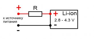
The simplest charger is a power supply with a resistance included in the circuit to reduce the charging current. Sometimes they also connect a timer that fires after a set time period has passed. All of these options are not conducive to long battery life.
Methods for charging LI Ion batteries for a screwdriver:
- Using a factory charger. Often it is also suitable for charging a new battery;
- Reworking the charger circuit, with the installation of additional circuit elements;
- Purchase of a ready-made memory. A good option is IMax.
Let's say there is an old Makita DC9710 charger for charging a 12 V Ni-Cd battery, which has an indication in the form of a green LED signaling the end of the process. The presence of a BMS board will allow you to stop the charge when the specified voltage limits per element are reached. The green LED will not light up, but the red one will simply go out. The charge is complete.
The Makita DC1414 T charger is designed to charge a wide range of 7.2-14.4 V batteries. In it, when the protective shutdown is triggered at the end of the charge, the indication will not work correctly. The red and green lights flash, which also signals the end of the charge.
The cost of replacing screwdriver batteries with lithium-ion ones depends on the power of the tool, the need to buy a charger, etc. But if the drill/driver is in good functional condition and the charger does not require major alteration or replacement, then for a couple of thousand rubles you can get an improved power tool with increased battery life.
Source:
Lithium battery assembly
Many owners of screwdrivers want to convert their batteries to lithium battery cells.
Many articles have been written on this topic and in this material I would like to summarize the information on this issue.
First of all, let's look at the arguments in favor of converting a screwdriver to lithium batteries and against it. We’ll also look at some aspects of the battery replacement process itself. The pros and cons of converting a screwdriver battery to lithium cells
First you need to think, do I need this alteration? After all, this will be an outright “homemade” and in some cases can lead to failure of both the battery and the screwdriver itself. Therefore, let's look at the pros and cons of this procedure. It is possible that after this some of you will decide to abandon converting the Ni─Cd battery for a screwdriver to lithium cells.
Pros
Let's start with the advantages:
- The energy density of lithium-ion elements is significantly higher than that of nickel-cadmium elements, which are used by default in screwdrivers. That is, a lithium battery will have less weight than a cadmium battery with the same capacity and output voltage;
- Charging of lithium battery cells occurs much faster than in the case of Ni─Cd. It will take about an hour to charge them safely;
- Lithium-ion batteries do not have a “memory effect”. This means that they do not have to be completely discharged before charging .
Now about the disadvantages and difficulties of lithium batteries.
Cons
- Lithium battery cells cannot be charged above 4.2 volts and discharged below 2.7 volts. In real conditions, this interval is even narrower. If you go beyond these limits, the battery can be damaged. Therefore, in addition to the lithium cans themselves, you will need to connect and install a charge-discharge controller in the screwdriver ;
- The voltage of one Li─Ion element is 3.6─3.7 volts, and for Ni─Cd and Ni─MH this value is 1.2 volts. That is, problems arise with assembling a battery for screwdrivers with a voltage rating of 12 volts. From three lithium cans connected in series, you can assemble a battery with a nominal value of 11.1 volts. Out of four ─ 14.8, out of five ─ 18.5 volts and so on. Naturally, the voltage limits during charge-discharge will also be different. That is, there may be problems with the compatibility of the converted battery with the screwdriver;
- In most cases, 18650 standard banks are used as lithium cells for conversion. They differ in size from Ni─Cd and Ni─MH cans. In addition, you will need a place for the charge-discharge controller and wires. All this will need to fit into a standard screwdriver battery case. Otherwise, it will be extremely inconvenient for them to work;
- A charger for cadmium batteries may not be suitable for charging the battery after it has been rebuilt. It may be necessary to modify the charger or use universal chargers ;
- Lithium batteries lose their functionality at low temperatures. This is critical for those who use a screwdriver outdoors;
- The price of lithium batteries is higher than cadmium batteries.
Source: https://akkummaster.com/vidy-akkumulyatory/akkumulyatory-dlya-elektrotehniki/peredelka-shurupovyorta.html
Converting a screwdriver to lithium, part two, charging correctly
Last time I told you how to properly remake a battery for a cordless tool. I also wrote that I would talk about the features of the charge, and the subject of the review this time will be the DC-DC converter board. If anyone is interested, please come visit. Initially, I planned to limit myself to two parts, reworking the battery and charger. But while I was preparing the review, an idea matured in my head for the third part of the review, a more complex one. And in this part I will tell you how you can remake your original transformer charger if it is still working, or if the power transformer is still alive.
The converter board was ordered quite a long time ago in the amount of several pieces (in reserve), it was ordered specifically for this alteration, because it has some features, however, I won’t go too far, let’s be consistent.
To begin with, I will divide chargers into three main types: 1. The simplest ones are a transformer, a diode bridge and several parts. Ultra-budget tools are equipped with such chargers. 2. Branded. Essentially the same thing, but it already includes simple “brains” that automatically turn off the charge at the end. 3. “Advanced” - switching power supply, charge controller, sometimes charging several batteries at the same time.
A tool from the first category rarely gets remade, since it is often easier (and cheaper) to buy a new one, while the third category usually has its own difficulties in remaking. In principle, it is possible to remake devices of the third group, but not within the scope of this article, since there are a lot of types of such chargers and each requires an individual approach.
This time I will remake the charger from the second group, a proprietary one, although simple. But this rework has much in common with the first group, and therefore will be useful to a larger number of readers.
In order to charge the battery, you need to not just connect it to the power supply; such an experiment usually does not end very well. You need to connect it to the charger. And here comes a slight misunderstanding, since quite a lot of people are accustomed to calling small power supplies from which they charge their smartphones, tablets and laptops chargers. These are not chargers, but power supplies.
What is the difference between a charger and a power supply? The power supply is designed to provide a stabilized voltage within the range of declared load currents. The charger is usually more complex, since its output voltage depends on the load current, which in turn is limited. In this case, the charger contains a unit that stops charging at the end, and sometimes also protection against connecting the battery in the wrong polarity.
The simplest charger is simply a power supply and a resistor (sometimes an incandescent lamp, which is even better) in series with the battery. This circuit limits the charging current, but as you understand, it cannot do anything else.
It’s a little more complicated when they also install a timer that turns off the charge after a certain time, but this principle quickly “kills” the batteries. For example, this is done in one of the inexpensive chargers for screwdrivers (photo not mine).
The next class comes from more “smart” chargers, although in essence they are not much better than the previous one. For example, here is a photo of a branded Bosch charger designed to charge NiCd batteries.
But all these chargers seem very simple after looking at the modern options for charging lithium batteries.
Of course, the last option does not quite fit into our concept of redesign, since it is desirable that our charger not only charges correctly, but also costs minimal money.
The chargers of Chinese screwdrivers look, of course, much simpler, but again, hardly anyone would want to make such a device from scratch, although this is exactly what I plan to do in the third part, albeit more correctly.
And so, to begin with, let’s assume that we have a charger on our hands that simply does not fit the new type of battery, but is serviceable. Well, or at least his transformer is working. As I wrote above, you can even use just a resistor or a light bulb, but this is “not our method.”
The schematic diagram of a typical inexpensive charger looks something like this: Transformer, diode bridge, thyristor and control circuit. True, sometimes instead of a thyristor there is a relay, the current is not limited in any way and there may be a thermal control circuit against overheating (although this does not always save.
But from this circuit we only need a transformer and a diode bridge, although we will have to add another capacitor, so we will get some initial unchanged part, it is marked in red and will not change further.
The diode bridge is usually located on the board and can be used if necessary (if it is working properly). Those. By and large, you can remove all radio elements from the board, leaving only four diodes and terminals for connecting the battery, and use the board itself as a base. The cathode of the diodes is marked with a stripe, the point where two terminals marked with a stripe are connected is a plus, respectively, the point of connection of the “unlabeled” terminals is a minus. A transformer is connected to the other two connection points.
True, when you open the charger, you can see the following picture (ignore the absence of a transformer): In this case, you will have to unsolder everything.
It is convenient to replace the diodes on the board with a ready-made diode bridge; a transformer is connected to the speaker terminals, + and -, respectively, go further into the circuit. Of course, you can tell how to choose a capacitor, but I advise you not to bother and put one like in the photo, capacity 1000 μF, voltage 35 Volts. The capacity can be larger, for example 2200, and the voltage is 50 or 63 Volts, a large capacity and voltage do not make sense, but will only increase the size of the capacitor. Any capacitor can be used, even a “noname” will do. Yes, it must be installed in any case, regardless of the serviceability of the diode bridge.
Now let’s move on to the charger itself, or rather to its variants; this node is marked with a rectangle in the last diagram. The simplest and at the same time relatively correct way is to install an LM317 voltage stabilizer chip.
But as I wrote above, the charge current must be limited. Yes, many circuits can not only limit, but also stabilize it, but by and large it does not matter to batteries whether the charge current is 1, 2 or 3 Amperes, it does not matter whether it is stable during the charging process or “floating”, it is important that the charge current does not exceed installed for batteries. Although for batteries that are used in screwdrivers it is difficult to exceed it, since they can operate not only at high discharge currents, but also at high charging currents. The simplest solution is to transfer the LM317 microcircuit from voltage stabilization mode to current stabilization mode, or more precisely, add a current stabilization mode. This is achieved by adding one resistor, as shown in the diagram. The resistor value is very easy to calculate: 1.25/I (current in Amperes) = R (resistor value in Ohms). For example, you need a current of 1.5 Amperes, then it will be 1.25/1.5= 0.83 Ohms.
The values of the voltage divider resistors are also quite easy to calculate, but I would advise placing a trimmer in series with the upper resistor in order to accurately set the voltage, since, unlike current, accuracy is important here. You can use a special calculator, but it is not very convenient, so I will offer values without it, for a voltage of 12.6 Volts (3 series batteries of 3.7 Volts) the upper resistor needs 1.5 kOhm, the trimmer in series with it is 200 Ohm, and the lower resistor is 13 kOhm.
I specifically indicated that the tuning resistor is placed in series with the upper resistor. In the event of a break, the output will have a minimum voltage. If you cut off the lower resistor, the output voltage will be maximum. By the way, in common DC-DC converter boards, the opposite is done; in the event of a break in the trimming resistor, they will output the maximum voltage.
Everything is good in the above scheme, simplicity, price, but the high power output negates all the advantages, since you will need a very impressive radiator, so it is not very suitable for high charging currents.
A more correct option would be to use a step-down DC-DC converter. For example this:
Of course, in its original form it will not limit the current, but if desired, it can be modified (in case it already exists). The modification is simple and I already described it in one of my reviews, although at the end I used it as an LED driver, but essentially it doesn’t matter. You need: 1 transistor type BC557 or any analogue (or even the well-known KT361 or KT3107) 2 resistors with a nominal value of 33-200 Ohms of any power. 1 resistor as a current shunt 1 ceramic capacitor 0.1 µF.
The current measuring resistor is calculated very simply, as in the case of LM317, only the values are slightly different. 0.6/I (current in Amps) = R (resistor value in Ohms). For example, you need a current of 1.5 Amperes, then it will be 0.6 / 1.5 = 0.4 Ohms.
The output of the additional circuit is connected to pin 4 of the LM2596 microcircuit; if another microcircuit is used, then we look for the pin marked as FB in the description and connect it to it.
In this embodiment, using a trimming resistor, we set the output voltage (at idle). True, such a scheme may slightly undercharge the batteries, although not much, but this is the price to pay for simplicity. To charge fully, you need to switch the voltage measurement input (one of the voltage divider resistors) to the output of the entire circuit.
All of the above charging methods are workable, but not very convenient. It would be more correct to use a board that “can” not only stabilize the output voltage, but also the current. For example, this scarf. It is very easy to distinguish suitable boards from others; the description should say “DC-DC StepDown”, and the board should have at least two interlinear resistors.
But in addition to adjusting the output current, this board has an additional bonus in the form of an indication: 1. An LED at the top shows the current limiting mode 2. A pair of LEDs at the bottom shows the end of the charge.
The battery charge indication is implemented very simply; the LEDs switch when the current drops below 1/10 of the initially set one. This mode of operation is very common and is used in many simple chargers. Those. for example, we set the charge current to 1.5 Amperes, connected the battery, when the charge current drops below 150 mA, one of the LEDs will go out and the second will light up, thereby indicating that the charging process is complete. Reviews of this board were done by a colleague of ksiman, so it’s easier to provide a link for a more detailed description.
The diagram of this board, also from the above review, may be useful.
It turns out that this board is quite well suited for charging batteries; first we set the end of charge voltage at the rate of 4.2 Volts per element, and then the charge current. For gourmets, you can offer the same board, but with an indication of the charge current and voltage on the battery, but in my opinion, in this case this is unnecessary. I reviewed this board, in fact this is a photo from that review, where I also showed how to make a switching power supply yourself.
This is what this option will look like on a block diagram.
So we slowly got to the subject of the review, which was primarily of interest due to its low price. I have very strong suspicions about the “proprietary” nature of the installed microcircuit, but if you do not use it for the entire declared 3 Amperes, then it is quite viable.
It so happened that initially I did not think of doing a review of this board, and although I bought 4 of them, I only had one left at home, and that one already had traces of my intervention. I desoldered the original LEDs and soldered others.
In its original form, there are three LEDs on the board: 1. Charged. 2. Charge 3. Current limit indication.
How does the indication work? The Charge and Charged LEDs are turned on so that only one of them lights up, so they can be considered as one. In boards without current regulation at which the indication will be triggered, switching occurs when the charging current drops below 1/10 of that set by the resistor - Current limitation. In the board under review, you can set an arbitrary operating current; I would recommend setting it to 1/5.
The current limit indication LED works slightly differently; it lights up when current limitation occurs, i.e. when the current at the set voltage tends to increase more than that set by the regulator. For example, we set the current to 1 Ampere and 10 Volts (conditionally), connected a load that at 10 Volts consumes 0.5 Amperes. The output will be 10 Volts 0.5 Amperes. Then we connected a load, which at 10 Volts will consume 1.5 Amperes, the output will be 1 Ampere and 8 Volts (conventionally), i.e. the board will reduce the voltage to a value at which the output current will not exceed the set one and at the same time the LED will light up.
There are also three trimming resistors on the board: 1. Adjustment of the output voltage. 2. Adjustment of the threshold for indicating the end of charge. 3. Adjustment of the output current limit threshold.
The board is very simple; it contains the LM2596 chip itself, a 78L05 stabilizer and an LM358 comparator. LM2596 is actually a PWM controller. 78L05 is used to power the comparator and as a voltage reference. LM358 “monitors” the current and simultaneously controls the display
A track on a printed circuit board acts as a current shunt. This method of measuring current is not very good, since the current will “float” depending on the temperature of the board, but since the stability of the output current does not matter for us, we can ignore this.
Location of contacts, controls and indications from the product page.
Boards with the ability to limit output current are very suitable for charging batteries. And those boards that have an indication of the end of the charge also allow you to get some convenience, allowing you to know that the battery is charged. But all of the above methods have one drawback: all these options cannot turn off the battery after charging is complete, i.e. stop the process completely. Of course they will tell me how the batteries live in uninterruptible power supplies. But here there is a peculiarity: some types of batteries have a concept - cyclic charging and the so-called Standby, i.e. supportive. The same lead battery is charged in cyclic mode to 14.3-15 Volts, and in standby mode only to 13.8-13.9 Volts.
If the battery is not disconnected, then a small charging current will always flow through it, and although lithium batteries are a little “lucky” in this regard, their current drops very significantly, but still, it is not recommended to leave them in this mode. The fact is that cadmium or lead ones simply begin to break down, heat up and that’s it, but with lithium ones a fire is possible. Yes, lithium batteries have a safety valve, but extra protection is never a bad thing.
The question is often asked - what about the protection board, because it can turn off the battery after charging is complete. It can and not only can, but it will turn it off, only it will do this not at 4.2 Volts per element, but at 4.25-4.35 Volts, since the shutdown function for it is more protective than the main one. Therefore, doing this is highly not recommended.
That’s actually why I came up with a simple circuit that will turn off the battery when the charge is complete. The operating principle is very simple (and therefore has some limitations). We connected the battery, since capacitor C1 is discharged, a current flows through it, which opens the transistor, and it supplies current to the relay. The relay connects to the charging battery, and then the relay is powered through an optocoupler, which is connected to the charge indication output of the converter board.
Accordingly, a small scarf was developed, and in a universal design.
Well, then everything is simple and familiar, we print the board on paper, transfer it to the PCB, and etch it. For those interested, the process of manufacturing printed circuit boards is shown in detail in this review.
When I came up with the circuit, I tried to simplify it as much as possible, using a minimum of components. 1. Relay - any with a winding voltage of 12 Volts (for options with 3-4 batteries) and contacts designed for a current of at least 2x the charging current. 2. Transistor - BC846, 847, or the well-known KT315, KT3102, as well as analogues. 3. Diode - any low-power diode. 4. Resistors - any in the range of 15 - 33 kOhm 5. Capacitor - 33-47 uF 25-50 Volts. 6. Optocoupler - PC817, found on most power supply boards.
Collected the fee.
I made the board universal; you can use a field-effect transistor instead of a relay; some of the components remain the same as before. In addition, this option is more universal, as it is suitable for screwdrivers with 3-4-5 batteries. But this board has a drawback. There is a “parasitic” diode inside the transistor, and if you leave the battery connected to the charger but unplug it, the battery will discharge through the charger circuit. In the version that I showed above, there will be a similar problem, but there the current is very small, about 0.5 mA, and it will take about 4000 hours for the battery to completely discharge.
Slightly different values are used here, although essentially only the value of resistors R4 and R5 is important. The value of R5 must be at least 2 times less than that of R4.
We select components for the future board. Unfortunately, you will most likely have to buy a transistor, since such devices are rarely used in finished devices; they can be found on motherboards, but extremely rarely.
The board is universal, you can use a relay and make it according to the previous circuit, or you can use a field-effect transistor.
Now the block diagram of the charger will look like this: Transformer, then diode bridge and filter capacitor, then the DC-DC converter board, and finally the shutdown board. I did not sign the polarity of the charge indication pins, since it can be different on different boards; if something doesn’t work, then you just need to swap them, thereby changing the polarity to the opposite.
Let's move on to the actual alteration. First of all, I cut the tracks from the output of the diode bridge, the battery connection terminals and the charge indication LED. The goal is to disconnect them from the rest of the circuit so it doesn't interfere with the "process". You can, of course, simply unsolder all the parts except the bridge diodes, it will be the same, but it was easier for me to cut the tracks.
Then we solder the filter capacitor. I soldered it directly to the diode terminals, but you can install a separate diode bridge, as I showed above. Remember that a terminal with a stripe is a plus, without a stripe a minus. The capacitor has a long lead - a plus.
The printed circuit boards on top did not fit at all, constantly resting against the top cover, so we had to place them from below. Here, of course, everything was not so smooth, they had to bite out one stand and saw down the plastic a little, but in any case, they were much better here. They even increased in height with a margin.
Let's move on to the electrical connections. To begin with, we solder the wires, at first I wanted to use thicker ones, but then I realized that I simply couldn’t turn around with them in a cramped case and took ordinary multi-core wires with a cross-section of 0.22mm.sq. I soldered the wires to the top board: 1. On the left is the power input of the converter board, connected to the diode bridge. 2. On the right - white and blue - the output of the converter board. If a disconnect board is used, then to it, if not, then to the battery contacts. 3. Red with blue - output indicating the charging process, if with a shutdown board, then to it, if not, then to the indication LED. 4. Black with green - Indication of the end of the charge, if with a disconnect board, then to the LED, if not, then we do not connect it anywhere.
So far only the wires to the battery are soldered to the bottom board.
Yes, I completely forgot, you can see the LED on the left board. The fact is that I completely forgot and unsoldered all the LEDs that were on the board, but the problem is that if you unsolder the current limit indication LED, the current will not be limited, so it must be left (marked on the board as CC/CV) , be careful.
In general, we connect everything as shown, the photo is clickable.
Then we glue double-sided tape to the bottom of the case, since the bottom of the boards is not entirely smooth, it is better to use thick tape. In general, everyone does this moment as conveniently as possible, you can glue it with hot glue, screw it with self-tapping screws, nail it 
We glue the boards and hide the wires. As a result, we should have 6 wires left free - 2 to the battery, 2 to the diode bridge and 2 to the LED.
Don’t pay attention to the yellow wire, this is a special case, I only had a 24 Volt relay, so I powered it from the converter input. When preparing wires, always try to follow the color coding, red/white is positive, black/blue is negative.
We connect the wires to the original charger board. Here, of course, everyone will have their own way, but I think the general principle is clear. You need to especially carefully check that the connection to the battery terminals is correct; it is better to first check with a tester where the plus and minus are; however, the same applies to the power input.
After all these manipulations, it is imperative to check and possibly reset the output voltage of the converter board, since during the installation process you can reset the setting and get at the output not 12.6 Volts (the voltage of three lithium batteries), but for example 12.79. You can also adjust the charge current.
Since setting the threshold for indicating the end of charge is not very convenient, I recommend buying a board with two trimming resistors, it’s easier. If you bought a board with three trimming resistors, then to configure it you need to connect to the output a load approximately corresponding to 1/10 - 1/5 of the set charge current. Those. if the charge current is 1.5 Amperes and the voltage is 12 Volts, then it can be a resistor with a nominal value of 51-100 Ohms with a power of about 1-2 Watts.
We've set it up and check it before assembly. If you did everything correctly, then when you connect the battery, the relay should activate and the charge will turn on. In my case, the indication LED goes out and turns on when the charge is complete. If you want to do the opposite, you can turn on this LED in series with the input of the optocoupler, then the LED will light while charging is in progress.
Since the title of the review still mentions the board, and the review is about redesigning the charger, I decided to check the board itself. After half an hour of operation at a charge current of 1 Ampere, the temperature of the microcircuit was about 60 degrees, so I can say that this board can be used up to a current of 1.5 Amperes. However, I suspected this from the very beginning; at a current of 3 Amps, the board will most likely fail due to overheating. The maximum current at which the board can still be used relatively safely is 2 Amperes, but since the board is in a case and the cooling is not very good, I recommend 1.5 Amperes.
That's it, we twist the body and set it to full run. I actually had to drain the battery before this, since I charged it in the process of preparing the last part. If a charged battery is connected to the charger, then the relay is activated for 1.5-2 seconds, then turns off again, since the current is low and blocking does not occur.
So, now about the good and the not so good. The good thing is that the conversion was a success, the charge is on, the board disconnects the battery, in general it’s simple, convenient and practical. The bad - If you turn off the charger's power during charging and then turn it on again, the charge will not automatically turn on. But there is a much bigger problem. During the preparation process, I used the board from the previous review, but I also wrote there that the board does not have a controller, and therefore cannot be completely blocked. But smarter boards completely turn off the output in a critical situation, and since it is also an input, when connected to the charger that I modified above, it will not start. Voltage is needed to start, and the board needs voltage to start 
There are several solutions to this problem. 1. Place a resistor between the input and output of the protection board, through which current will flow to the terminals to start the charger, but I don’t know how the protection board will behave, there is nothing to check. 2. Connect the charger input to a separate battery terminal, this is often done with cordless tools with lithium batteries. Those. We charge through some contacts, discharge through others. 3. Do not install a shutdown board at all. 4. Instead of automation, install a button as in this diagram.
At the top there is an option without a protection board, at the bottom there is just a relay, an optocoupler and a button. The principle is simple, we inserted the battery into the charger, pressed the button, the charge began, and we went to rest. Once the charge is complete, the relay will completely disconnect the battery from the charger.
Conventional chargers constantly try to supply voltage to the output if it is below a certain value, but this modification option is inconvenient, and with a relay it is not very applicable. But for now I think it might be possible to do it beautifully.
What can you advise regarding the choice of battery charging options: 1. Just use a board with two trimming resistors (it is in the review), it’s simple, quite correct, but it’s better not to forget that the charger is on. I don’t think there will be any problems for a day or two, but I wouldn’t recommend going on vacation and forgetting the charger is on. 2. Do as in the review. Difficult, with limitations, but more correct. 3. Use a separate charger, for example the well-known Imax. 4. If your battery has an assembly of two or three batteries, then you can use B3. It is quite simple and convenient, in addition, there is a full description in this review from the author Onegin45.
5. Take the power supply and modify it a little. I did something similar in this review.
6. Make your own charger, with all automatic shutdowns, correct charging and extended display. The most difficult option. But this is the topic of the third part of the review, however, it will most likely also include converting the power supply into a charger.
7. Use a charger like this.
In addition, I often encounter questions about balancing the elements in the battery. Personally, I think that this is unnecessary, since high-quality and selected batteries are not so easy to unbalance. If you want something simple and high quality, then it’s much easier to buy a protection board with a balancing function.
Recently there was a question whether it is possible to make the charger able to charge both lithium and cadmium batteries. Yes, it can be done, but it’s better not to, since in addition to different chemistry, batteries also have different voltages. For example, an assembly of 10 cadmium batteries requires 14.3-15 Volts, and an assembly of three lithium batteries requires 12.6 Volts. In this regard, you need a switch that you can accidentally forget to switch. A universal option is only possible if the number of cadmium batteries is a multiple of three, 9-12-15, then they can be charged as lithium assemblies 3-4-5. But common tool batteries cost assemblies of 10 pieces.
That seems to be all, I tried to answer some questions that people ask me in private. In addition, the review will likely be supplemented with answers to your next questions.
The purchased boards are quite functional, but the chips are most likely fake, so it is better to load no more than 50-60% of the declared value.
In the meantime, I’m thinking that you need to have it in a proper charger, which will be made from scratch. So far the plans are: 1. Automatic start of charging when installing the battery 2. Restart in case of power failure. 3. Several stages of charging process indication 4. Select the number of batteries and their type using jumpers on the board. 5. Microprocessor control
I would also like to know what would be interesting for you to see in the third part of the review (you can PM me).
I wanted to use a specialized microcircuit (it seems that you can even order a free sample), but it only works in linear mode, and this causes heating :((((
It might be useful to have a link to an archive with traces and diagrams, but as I wrote above, the additional board most likely will not work with boards that completely disconnect the batteries.
In addition, such conversion methods are only suitable for batteries up to 14.4 Volts (approximately), since chargers for 18 Volt batteries produce voltages above 35 Volts, and DC-DC boards are designed only up to 35-40.
Converting a screwdriver to 18650 lithium batteries
> Tools > Converting a screwdriver to 18650 lithium batteries
The industry has been making screwdrivers for a long time, and many people have older models with nickel-cadmium and nickel-metal hydride batteries. Converting a screwdriver to lithium will improve the performance characteristics of the device without buying a new tool. Now many companies offer services for converting screwdriver batteries, but you can do it yourself.
Converting a screwdriver to lithium batteries
What precautions should be taken to avoid damaging the lithium battery?
- Due to technology limitations, the charge level of lithium batteries is not expected to be higher than 4.25-4.35 V. The discharge should not reach 4.5-2.7. This condition is indicated in the technical data sheet for each specific model. If these values are too high, you can easily damage the device. Special charging and discharging controllers are used, which keep the voltage on the lithium cell within the normal range. Converting the screwdriver to a lithium battery
with a controller will protect the device from failure during operation. - The voltage of lithium batteries is a multiple of 3.7 V (3.6 V). For Ni-Mh models } the myth indicator is 1.2 V. This phenomenon is understandable. The nominal voltage in lithium devices is stored in a separate cell. lithium battery
will never be assembled. The rating will be 11.1 V (three consecutive cells) or 14.8 V (four consecutive cells). Additionally, the voltage indicator of the lithium cell changes during operation when the working version is charged at 4.25 V, and when the working version is discharged. at 5.5 V. Converting a screwdriver to a lithium battery with 14.8 V - four screwdrivers. The voltage indicator 3S (3 serial. three serial connections) will change during operation of the device from 12.6 V (4.2x3) to 7.5 V (3.5.5x3). For the 4S configuration } myth the indicator ranges from 16.8 to ten V. - Converting a screwdriver to eighteen thousand six hundred fifty lithium batteries (most products have this exact size) requires taking into account the difference in dimensions with Ni-Mh cells. The diameter of the eighteen 650 cell is eighteen mm, and the height is sixty-five mm. It is of great importance to calculate how many cells will fit in the case. At the same time, you should remember that for a model with a power of 11.1 V you need a number of cells that is a multiple of three. For a model with a power of 14.8 V - four. The controller must also fit, not the patching wires.
- The charging device for a lithium-based battery differs from the device for Ni-Mh modifications.
The text of the article will discuss how a screwdriver is converted to Li-Po lithium batteries. The tool is equipped with a Ni-Mh- pair with a voltage rating of twelve V and a capacity of 5.6 Ah. Hitachi screwdriver conversion will be considered. Lithium batteries will provide the device with long-term service.