Kinds
Floors on the ground: types of structures, features and installation technology in a private house with your own hands
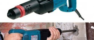
Rotary hammers from Bosch are divided into types:
Household models (engines 410-720 watts). Such units have three standard modes, their weight is small (no more than six kilograms).
The letter “P” identifies the model as a unit for domestic use. Typically, such a tool is marked with a green color. The disadvantage of such machines is not the best cooling and increased efficiency.
Such models have much more advantages than disadvantages, among which it is worth mentioning:
- average price;
- light weight;
- compact dimensions;
- good performance;
- reliability in operation.
The advantages of this model are effective cooling of the unit, minimal vibration, and operational reliability. If we talk about the disadvantages, we should mention the large size of such devices and the high price.
- Hammer drill. It has the following technical indicators: power – up to 1.6 kW;
- rotation – no more than 3980 revolutions;
- the number of beats is about 50 per minute.
Disassembly procedure for a Bosch 2-26 rotary hammer
Drilling machine bosch pbd 40: customer reviews, characteristics
Since the disassembly procedure for Bosch rotary hammers is 2-20; 2-24; 2-26 is almost the same, let’s consider the order of disassembly using the Bosch 2-26 rotary hammer as an example.
Disassembling the Bosch GBH 2-26 dre hammer drill begins with disassembling the quick release chuck.
Disassembling the quick release chuck
Bosch rotary hammers most often use two types of chucks: SDS-plus chucks and SDS-max chucks. The difference between them is the principle of clamping the tail part of the working organ.
The design of the Bosch hammer drill chuck differs in the design of the tool mounting rods depending on the SDS-plus or SDS-max model. In addition to the listed types of cartridges, there are SDS-top and SDS-quick cartridges.
Difference between cartridge mounting points
The procedure for disassembling the Bosch 2-26 hammer drill chuck is simple:
- remove the rubber tip pos. 34;
- remove the retaining ring pos. 87;
- remove the steel washer pos. 833;
- remove the conical spring pos. 833;
- Carefully, so as not to lose it, using a magnet, remove the barrel balls pos. 89.
SDS-plus cartridge
Carefully inspect all parts of the cartridge.
SDS-plus quick-release chuck in disassembled state
SDS-plus chucks were developed specifically for drilling tools. The diameter of the tool shanks is 10 mm, the length of the working tool is in the range of 110...1000 mm. The diameter of the drills lies in the range of 4…26 mm.
How to remove the mode switch
With the hammer on its side, remove the mode switch pos. 832.
First, turn the switch to the “Drilling” position, press the screwdriver all the way into the end of the switch button (it is red) and turn the switch counterclockwise to an angle of 70º.
While rocking the switch handle, pull the switch handle out of the housing.
Disassembling the impact mechanism assembly
Having placed the Bosch 2-26 hammer drill vertically on the handle, unscrew the four screws pos. 90 holding the cover of the mechanical assembly housing.
Press the end of the impact shaft and remove the cover. The lid is black plastic.
Now you need to remove the barrel pos. 821 and the intermediate shaft pos. 826. They are not secured by anything.
Next, using a screwdriver, you need to remove the bracket pos. 48 of the rolling bearing pos. 830. By the way, in simple terms it is called a “drunk bearing”. The following are removed sequentially: the sleeve pos. 26 and the “drunk bearing”.
We got to the drunken bearing
Disassembling the hammer mechanism barrel assembly
- dismantling the Bosch hammer drill barrel assembly begins from the side of the cavity, removing from it the cylinder pos. 26 with the hammer pos. 27;
- you need to remove the hammer assembly from the cavity;
- on the side of the chuck shaft, remove the lock ring pos. 85, the steel ring pos. 38 and another lock ring pos. 85;
- remove the spur gear pos. 22.
Impact mechanism assembly, intermediate shaft and bearing
Disassembling the cylinder
A hammer, pos. 27, is inserted inside the cylinder, from which the rubber ring, pos. 73, must be removed. During any disassembly, rubber parts must be replaced.
At the opposite end of the cylinder, a hinge, pos. 29, and two flat washers, pos. 41, are inserted.
Disassembling the intermediate shaft
The intermediate shaft is disassembled by removing the shaft, pos. 24, and pulling out the “drunk bearing” from the housing, pos. 77.
Bearings are removed with pullers or manually using a device.
How to repair any Bosch rotary hammer with your own hands, knowing the design features
The most widespread among professional builders in Russia are Bosch rotary hammers, and among amateurs the household models Bosch 2–20, 2–24, 2–26.
Rotary hammers not only work well, but are also easy to repair. You can easily find any broken part on them.
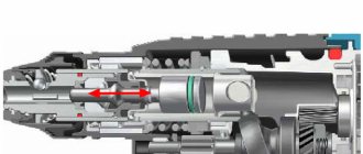
The designs of the described rotary hammers are based on the same principle: transmitting torque from the rotor to the shaft of the impact block barrel while simultaneously transmitting a translational impulse to the working tool.
Structurally, hammer drills are made according to the same design, but individual components or parts have their own characteristics.
If you know the specific differences between the models of the described Bosch rotary hammers, then disassembling and repairing them yourself will not be difficult.
Along with the originals, there are a large number of counterfeit tools on the Russian market, including Bosch rotary hammers.
Below we describe the design features of the models and how to disassemble and repair them yourself.
Operating principle of a Bosch rotary hammer
The operating principle of rotary hammers is the same, but the design features differ.
The main parts used in the listed models of Bosch rotary hammers are interchangeable. This applies to the mechanical and electrical components.
But there are units made that differ in the parts used.
To repair a Bosch 2-20, 2-24, 2-26 rotary hammer, you need to know these differences. Knowledge of the design features of each rotary hammer facilitates the repair process, finding breakdowns and eliminating them.
The designs of Bosch rotary hammers are so simple that they allow you to perform simple repairs, practically with your own hands, and replace any part without contacting service departments. You must have assembly skills, have basic knowledge of electrical engineering and understand the principle of operation of a rotary hammer.
The main differences in the designs of Bosch rotary hammers
When repairing a Bosch rotary hammer, you cannot do without an electrical diagram and a disassembly diagram for the tool of the model you are going to repair.
The electrical circuits of Bosch 2-20, 2-24, 2-26 rotary hammers are almost the same. Although there are some unprincipled differences.
But mechanical blocks are equipped with parts that differ structurally from each other. The main differences are concentrated in two units: the intermediate shaft and the barrel shaft of the shock block.
The greatest differences are presented in the design of the intermediate shaft, the “drunk bearing” assembly, and the mode switch. Unprincipled features are present in the design of the barrel of the striker block, firing pin, and striker.
Let's start with the Bosch 2-20 rotary hammer.
Diagram and design of the Bosch 2-20 rotary hammer
Repairing a Bosch 2–20 rotary hammer is not possible without knowledge of the design of the tool being repaired.
The operating principle of the Bosch 2–20 rotary hammer is based on the transmission of torque from the rotor shaft, pos. 3, to the shaft of the impact block, pos. 22, through the intermediate shaft, pos. 824, while simultaneously transmitting a longitudinal impulse to the working tool.
Rotor pos. 3 transmits torque to the helical gear of the intermediate shaft pos. 824.
Diagram of a Bosch 2-20 rotary hammer
The helical gear is mounted on the intermediate shaft and transmits rotational torque to the shaft. A fixed bearing is attached to the shaft, receiving rotational torque through the clutch. Due to its design, the drunk bearing transmits translational motion to the barrel cylinder of the impact mechanism.
Design of the intermediate shaft of the Bosch 2–20 rotary hammer
The intermediate shaft of a Bosch 2–20 rotary hammer consists of a rolling bearing assembly (drunk bearing), a clutch, a large helical gear, and a small spur gear.
Most often, breakdowns manifest themselves in wear of the clutch splines, which leads to the loss of rotation of the hammer drill chuck in the presence of a shock pulse.
It can be corrected by replacing the clutch or restoring the teeth of the clutch parts.
View of the intermediate shaft of the Bosch 2-20 rotary hammer
Design features of the Bosch 2–24 rotary hammer
It is best to start repairing a Bosch 2–24 rotary hammer by becoming familiar with the circuit and design features of the tool being adjusted. The operating principle of the Bosch 2–24 rotary hammer is similar to the operating principle of the Bosch 2–20 rotary hammer.
The torque is transmitted to the tool mounting shaft, simultaneously with the transmission of the shock impulse. The hammer drill has three operating modes: drilling with impact, drilling without impact, impact.
The helical gear of the rotor pos. 803 transmits torque to the helical gear of the intermediate shaft pos. 826.
Diagram of a Bosch 2-24 rotary hammer
Design of the intermediate shaft of the Bosch 2-24 rotary hammer
The intermediate shaft of the Bosch 2-24 rotary hammer consists of a rolling bearing assembly, pos. 830, a clutch, pos. 823, and a switching part, pos. 44. Most often the clutch fails. The teeth in it wear out. Repair of the coupling consists of correcting the profile of the engagement tooth in the coupling and on the intermediate shaft.
Bosch 2-24 hammer drill intermediate shaft assembly
Impact mechanism barrel shaft design
The barrel shaft of the impact block is designed to transmit a rotational impulse with simultaneous movement of the striker.
Rotation is transmitted from the spur gear of the intermediate shaft to the large spur gear pos. 22 of the barrel shaft pos. 821.
The reciprocating motion is transmitted through the driven bearing pos. 830, the impact piston pos. 26, the striker pos. 27, the impact bolt pos. 28 to the drill fixed in the chuck pos. 756.
The design is a shaft, hollow on one side. Parts are installed on the shaft on both sides.
From the side of the cartridge mounting, a spur gear, pos. 22, is installed on the shaft and fixed on the shaft using a roller, pos. 88, and pressed against the shaft collar with a spring, pos. 80. The spring itself is fixed with a locking ring pos. 85.
The following is inserted into the cavity of the impact block barrel shaft: the assembled impact bolt pos. 28 and the impact piston. The striker pos. 27 is inserted into the impact piston pos. 26 with a new rubber ring pos. 73 placed on it. All rubber products are lubricated with the recommended lubricant.
Malfunctions of the hammer shaft shaft
Due to the weakening of the spring force and the locking roller falling out, the gear may rotate on the shaft. This manifests itself in the disappearance of the torque with the presence of a shock pulse.
The rotary hammer hammers, but does not drill
When rubber products (sealing rings) wear out, the hammer drill stops working in the “Slotting” mode. This happens gradually. The impact force weakens as the rubber rings wear. The thing is that from the drunk bearing the movement is transferred to the impact piston pos. 26, in which the striker pos. 27 creates air pressure and acts on the impact bolt pos. 28.
The hammer drills, but does not chisel
If you apply a lot of force when operating a hammer drill, this can lead to the destruction of the impact bolt and jamming of the striker in the impact piston. Such malfunctions can only be eliminated by completely replacing the failed part. Learn more about troubleshooting a Bosch rotary hammer.
Design features of the Bosch 2–26 rotary hammer
Repair of a Bosch 2–26 rotary hammer should begin with familiarization with the design features of the tool being adjusted. The operating principle of the Bosch 2–24 rotary hammer is similar to the operating principle of the Bosch 2–26 rotary hammer.
Diagram of a Bosch 2-26 rotary hammer
Rotation is transmitted from the rotor shaft, through the intermediate shaft, to the shaft of the impact barrel. At the same time, a bearing mounted on the intermediate shaft transmits reciprocating motion to the impact piston.
The hammer drill has three operating modes: drilling with impact, drilling without impact, impact.
The helical gear of the rotor pos. 803 transmits torque to the helical gear of the intermediate shaft pos. 823.
The intermediate shaft is similar to the shaft in the design of the Bosch 2–24 rotary hammer and is interchangeable with parts included in the intermediate shaft of the Bosch 2–24, 2–26 rotary hammers. Instructions for disassembling a Bosch rotary hammer.
Conclusions:
- Knowing the differences between the above models of Bosch rotary hammers will allow you to quickly disassemble the tool and replace faulty parts. To do this, you do not need to contact customer service.
- Structurally, Bosch rotary hammers are so simple that they allow you to carry out repairs of almost any complexity.
- All you need is desire and basic knowledge of mechanics.
It happens that you come across counterfeit models of Bosch rotary hammers. Read more about this here.
about disassembling a Bosch rotary hammer
: How to repair a hammer drill / 2-24 / How to change the impact bolt / Drunk bearing / Maintenance / Repair
Source: https://sdelalremont.ru/osobennosti-konstrukcij-bytovyx-perforatorov-bosch-2-20-2-24-2-26.html
Anchor structures of various types of drilling rigs
Anchor. It is the rotating unit of any induction motor. Considering that during operation the hammer drill experiences significant resistance to the material it destroys, the loads on the rotor often reach extraordinary values. Sometimes they cause a significant reduction in valve speed, resulting in immediate engine failure.
The resistance of fittings on a hammer drill to combustion is determined by its design. There are two types of perforation anchors:
- With wound rotor.
- Rotor cell proteins.
The short circuit of the armature winding is formed by rods, which, when assembling the rotor, fit into the grooves of its core. In this case, the ends of the rods are connected by a special rotor ring. This design has no moving contacts, which has a positive effect on the durability of the assembly.
The disadvantage of the armature of this design is the limited starting torque, which in relation to hammer drills requires limiting the intensity of use at the initial time after turning on the tool. Of course, this is impossible to keep in mind, so if you use the hammer drill carelessly, the longevity of the protein cell motor will be low.
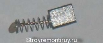
The problem is solved by installing electric motors of protein cells on all rotating hammers. The number of poles of the armature winding in this case fully corresponds to the same parameters of the stator, and the contacts of each phase are brought out into the external circuit using carbon-graphite brushes. Replacing the brush. This is a relatively simple process that you can perform (for out-of-warranty equipment) yourself. In other cases, you should use the services of specialists. Often the price of this type of service is associated with the need for static and dynamic balancing of the armature on a drill, which uses special technologies and equipment.
Device motor
The engine, being the main element of the device, drives all other parts of the mechanism. It consists of a stator and a rotor, with the rotor being a moving part and the stator not. The rotor includes an armature and a commutator. An anchor is a block containing steel plates. Windings of copper wire are wound on them. The collector, in turn, looks like a cylinder. Its design has the form of a dielectric with installed conductive plates; the armature windings are connected to these plates.
Read also: Operating principle of a digital oscilloscope
Rotation of the rotor occurs due to the magnetic flux created around it by the stator windings and leading to the occurrence of a torsional moment. In this case, the rotor uses only a constant current value, and the magnetic flux is always directed only in one direction. Power is supplied through brushes made of graphite. The brushes are arranged in such a way as to ensure electrical contact with the armature.
The wear of the brushes should not exceed 70 percent; if it exceeds, they need to be replaced. Before replacing, pay attention to the brush holder and clean it if necessary.
You can use a multimeter to check the windings. To do this, one probe of the measuring device is installed on the brush holder, and the second on the input for connecting to the 220 volt network. To accurately determine the connection locations, it is easier to use an electrical diagram. If the resistance is infinite, it is concluded that the winding has burned out.
The operating resistance of the stator winding is in the range of 18–32 Ohms. For example, the popular Interskol P-26/800ER hammer drill has a resistance of 28 Ohms. When replacing the stator, you will need to disassemble the motor. Usually four screws are unscrewed, the housing is moved apart in opposite directions, and access to the engine components is freed.
The rotor is fixed in the gearbox. It is checked for short circuits with a special device. Often, by visual inspection, you can conclude about its integrity. The rotor should not be scratched or blackened, and the plates should be clean. When replacing the rotor, it is important to properly connect the bearing to the rubber gasket.
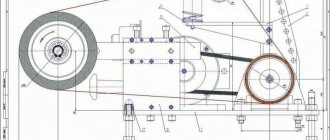
The design of a rotary hammer with a vertical (barrel) electric motor is slightly complicated due to the indirect transmission of torque. Therefore, with this type, a gearbox is used, which increases the impact and torque of the device.
Disassembling the hammer drill
The case of most devices is made of two halves: rear and front. They are tightened together using screws located parallel to the direction of the drill installation axis. But it happens that the halves are attached using side fastenings. Before unscrewing the fastening element connecting the halves of the housing, you will need to remove the cartridge.
The cartridge used corresponds to the SDS-plus or SDS-Max standard. To disassemble it you will need a flat-head screwdriver. At the first stage, the chuck clamp is released from the installed drill. If the mechanism itself is jammed and cannot be untwisted, then you should tap it in a circle with gentle blows of a rubberized hammer. It would not hurt to apply flushing fluid. At the next stage, the plastic casing is pulled down and the rubber boot is removed with a screwdriver. After this, all that remains is to remove the retaining ring, using a screwdriver, and remove the spring with the ball and the retaining plates.
When the cartridge is removed, the housing parts are removed. When disassembling the tool, you should be careful, remembering the order in which the elements are removed and their location. If there is a cover on the handle, you should remove it too. After that, all that remains is to carefully separate the housing and gearbox in different directions. Using the resulting gap, the switch button is removed. The brush holder is removed.
The button for setting operating modes, despite the types of devices, is removed in the same way. The switch is set to the strike position (shown on the body as a hammer), after which it is slightly pryed and turned counterclockwise one or two centimeters. Then, the switching pad is removed by pulling it towards you and the seat is freed up.
How to Disassemble a Bosch Drill
- breakdown of motor parts (stator, armature) - wear of the brushes or their burning - breakdown of the regulator and reverse switch - wear of the support bearings - poor clamping in the tool chuck.
Changing brushes
. A common type of breakdown is wear of the motor brushes, which are replaced independently by yourself. From time to time, there is an option to change the brushes without disassembling the drill body. For some models, it is enough to unscrew the plugs from the installation windows and install new brushes. For other models, changing requires disassembling the housing; in this case, you need to carefully remove the brush holders and remove the worn brushes, among them.
Do not wait until the brushes wear down to small size. This is fraught with the fact that the gap between the brush and the collector plates increases. Naturally, excessive sparking occurs, the collector plates become very hot and there are variations of “retreating” from the base of the collector, which will lead to the need to change the armature.
There is an option to determine the need to change the brushes by excessive sparking, which can be seen in the ventilation slots of the housing. The second method of determination is the random “jerking” of the drill during operation.
Power cord
. The cord is checked with an ohmmeter, one probe is connected to the contact of the power plug, the other to the core of the cord. Lack of resistance indicates a break. Then repairing the drill comes down to replacing the power cord.
Electric motor diagnostics
. In second place, in terms of the number of drill breakdowns, there is an option to put the malfunction of motor parts and, in most cases, the armature. Breakage of the armature or stator occurs for two reasons. incorrect operation and poor wiring. Domestic manufacturers with a worldwide reputation use expensive coil wire with double insulation with heat-resistant varnish, which significantly increases the reliability of the engines. Accordingly, in cheap models the quality of insulation of the winding wire is not sufficiently civilized. Incorrect operation boils down to frequent overloading of the drill or prolonged operation without breaks to cool the motor. Repairing a drill in makeshift conditions by rewinding the armature or, in other words, the stator, in this case is not feasible without special devices. Only 100% replacement of the element (only experienced repairmen will rewind the armature or stator at home).
Bosch PSB 550 RE (Drill)
To change the rotor or stator you need to disassemble
housing, disconnect the wires, brushes, remove the drive gear as necessary, and remove the engine completely along with the support bearings. Replace the faulty element and install the engine at its destination.
An armature malfunction can be detected by a corresponding smell, an increase in spark formation, and the sparks have a radial movement in the direction of the armature movement. Pronounced “burnt” windings are found during visual inspection. If the engine power has dropped, but there are no signs listed above, then you should contact the measuring devices. ohmmeter and megohmmeter.
The windings (stator and armature) are subject to only three types of damage. interturn electronic breakdown, breakdown to the “case” (magnetic circuit) and winding breakage. A breakdown on the housing is determined quite easily, just use the probes of a megohmmeter to touch any winding output and magnetic circuit. A resistance of more than 500 MΩ indicates the absence of breakdown. It should be noted that measurements should be carried out with a megger, which has a measuring voltage of approximately 100 volts. When making measurements with a simple multimeter, it is impossible to determine for sure that there is definitely no breakdown, but it is determined that breakdown definitely occurs.
Operating rules or how to protect the device from damage
To ensure long-term and efficient operation of an electric hammer drill, it is enough to follow a few simple rules. In particular:
- When working, it is not advisable to put too much pressure on the tool; at least this is not necessary, and moreover, with excessive pressure, the tool will fail faster.
- It is not permissible to operate the electric hammer drill in idle mode.
- When working with porous materials, it makes sense to turn off the impact mechanism. When working with particularly hard materials, it is advisable to use a lubricant.
- When working, especially for a long time, it is necessary to monitor the heating of the housing, especially in the place where the gearbox is installed. If there is noticeable heating, you must stop the work and wait until it cools down. Water cannot be used for cooling; its use may damage gearbox parts.
- Work with the tool should be carried out in the following mode - at least a 10-minute break after half an hour of work.
Specifications
The Bosch hammer drill is a tool that is especially popular among professional builders. These units rarely have to be seriously repaired, but, like any equipment, Bosch rotary hammers eventually require preventive repairs.
Bosch units are divided into two large classes:
- hammer drills in which the engine is horizontal (the layout of the barrel and armature are parallel);
- hammer drills, where the engine stands vertically - in this case, all working components are located at a certain angle.
The hammer drill has mechanical and electrical units. The second block consists of the following nodes:
- engine;
- engine control device;
- button and switch block;
- replaceable cord;
- block that reduces interference.
The mechanical assembly is assembled from the following elements:
- gearbox (mounted directly on the engine shaft);
- mechanism providing shock impulse;
- cartridge, brushes, anchor;
- a clutch that provides traction.
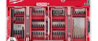
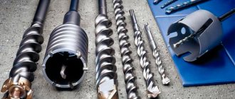
Also, along with the hammer drill itself, the kit includes various replaceable removable elements:
- drill;
- borax;
- crowns;
How to repair any Bosch rotary hammer with your own hands
The most widespread among professional builders in Russia are Bosch rotary hammers, and among amateurs the household models Bosch 2-20, 2-24, 2-26. Rotary hammers not only work well, but are also easy to repair. You can easily find any broken part on them.
The designs of the described rotary hammers are based on the same principle: transmitting torque from the rotor to the shaft of the impact block barrel while simultaneously transmitting a translational impulse to the working tool.
Structurally, hammer drills are made according to the same design, but individual components or parts have their own characteristics.
If you know the specific differences between the models of the described Bosch rotary hammers, then disassembling and repairing them yourself will not be difficult.
Along with the originals, there are a large number of counterfeit tools on the Russian market, including Bosch rotary hammers. Below we describe the design features of the models and how to disassemble and repair them yourself.
The operating principle of rotary hammers is the same, but the design features differ.
The main parts used in the listed models of Bosch rotary hammers are interchangeable. This applies to the mechanical and electrical components.
But there are units made that differ in the parts used.
To repair a Bosch 2-20, 2-24, 2-26 rotary hammer, you need to know these differences. Knowledge of the design features of each rotary hammer facilitates the repair process, finding breakdowns and eliminating them.
The designs of Bosch rotary hammers are so simple that they allow you to perform simple repairs, practically with your own hands, and replace any part without contacting service departments. You must have assembly skills, have basic knowledge of electrical engineering and understand the principle of operation of a rotary hammer.
Design of the intermediate shaft of the Bosch 2-20 rotary hammer
The intermediate shaft of a Bosch 2-20 hammer drill consists of a rolling bearing assembly (drunk bearing), a clutch, a large helical gear, and a small spur gear.
Most often, breakdowns manifest themselves in wear of the clutch splines, which leads to the loss of rotation of the hammer drill chuck in the presence of a shock pulse.
It can be corrected by replacing the clutch or restoring the teeth of the clutch parts.
Design features of the Bosch 2-24 rotary hammer
It is best to start repairing a Bosch 2-24 rotary hammer by becoming familiar with the circuit and design features of the tool being adjusted. The operating principle of the Bosch 2-24 rotary hammer is similar to the operating principle of the Bosch 2-20 rotary hammer.
The torque is transmitted to the tool mounting shaft, simultaneously with the transmission of the shock impulse. The hammer drill has three operating modes: drilling with impact, drilling without impact, impact.
The helical gear of the rotor pos. 803 transmits torque to the helical gear of the intermediate shaft pos. 826.
Design features of the Bosch 2-26 rotary hammer
Repair of a Bosch 2-26 rotary hammer should begin with familiarization with the design features of the tool being adjusted. The operating principle of the Bosch 2-24 rotary hammer is similar to the operating principle of the Bosch 2-26 rotary hammer.
Rotation is transmitted from the rotor shaft, through the intermediate shaft, to the shaft of the impact barrel. At the same time, a bearing mounted on the intermediate shaft transmits reciprocating motion to the impact piston.
The hammer drill has three operating modes: drilling with impact, drilling without impact, impact.
The helical gear of the rotor pos. 803 transmits torque to the helical gear of the intermediate shaft pos. 823.
The intermediate shaft is similar to the shaft in the design of the Bosch 2-24 rotary hammer and is interchangeable with parts included in the intermediate shaft of the Bosch 2-24, 2-26 rotary hammers. Instructions for disassembling a Bosch rotary hammer.
How the tool works
Literally, the word perforator means “drill hammer.” To increase productivity in mining operations, the jackhammer was developed in the early 19th century. The principle of operation of the device was to use a flywheel. He set in motion a bar with special tucks attached to it. The rod, under the influence of a spring, struck and returned back with a piston.
The device was constantly improved. In 1932, in Germany, the Bosch Corporation released the first rotary hammer powered by electricity. This device combined impact and torque. The operating principle developed by the company is still used in modern models of electric hammer drills.
A rock drill is a device designed to drill holes and destroy hard rock. Drills of different diameters and chisels are used as consumables. The tool is divided by application class:
- domestic;
- semi-professional;
- professional.
In addition, it is distinguished by its operating mechanism, which can be electromagnetic or pneumatic. The last type of mechanism is available in one-, two-, and three-mode. That is, you can perform drilling, striking, or both operations simultaneously.
The tool resembles a pistol in appearance and can be operated with an electric, fuel or pneumatic drive. The latter are in demand under hazardous working conditions, during which there is a possibility of explosion.
The operating principle of a hammer drill, which distinguishes it from other similar tools, is based on the impact mechanism. The electromagnetic type uses two electromagnetic coils to provide reciprocating motion of the core. It transfers inertia to the drill shank. The pneumatic type is based on the movement of a piston in a cylinder, which also performs reciprocating movements.
Each manufacturer strives to improve the design through the use of design features. These are mainly minor modifications related to the use of various materials and their location. In general, the main elements remain unchanged. Such details include:
- power button;
- engine;
- impact mechanism;
- safety clutch;
- drill clamp.
Additional design features include a dust removal system and a vibration suppression unit. For a multi-mode type of tool, a work switching button is installed.
Possible electrical faults
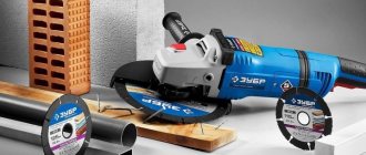
Malfunctions of the electrical part of a Bosch angle grinder can be divided into simple and complex.
Simple malfunctions of the electrical part of the Bosch angle grinder
If you turn on the angle grinder and it refuses to work, start looking for the problem with a broken power supply wire. Most often, a wire break appears at the entry point into the angle grinder or into the plug. Avoid twisting, as this will cause a short circuit in the tool.
To determine such a malfunction, it is necessary to open the covers of the grinder handle. In Bosch angle grinders up to 1000 W, the lid is secured with one screw at the end. For Bosch angle grinders over 1000 W, the handle cover is secured with several screws.
Using a tester, test the power circuit from the input plug pos. 5 to the switch. If the circuit is intact, proceed to check the operation of the switch. Bosch angle grinders use simple switches controlled by a power lever.
But the electrical contacts of the switch burn out and cause the grinder to fail. It is not practical to restore the contacts of the plastic switch; it must be replaced with a new one.
If the switch is intact, use a tester to check the presence of a circuit from each pin of the plug to each carbon brush. If the circuits are intact, the angle grinder should turn on. If it does not rotate, then there is a mechanical fault. Gears may jam or bearings may be damaged.
Checking the electric motor
If your Bosch grinder picks up speed regardless of you, starts to get very hot and sparks, you need to pay attention to the integrity of the rotor and stator windings. An involuntary increase in engine speed indicates a malfunction of the stator windings. The integrity of the windings is checked with a tester, and a short circuit between the turns is checked with a special device
An involuntary increase in engine speed indicates a malfunction of the stator windings. The integrity of the windings is checked with a tester, and a short circuit between the turns is checked with a special device.
How to determine whether a rotor is faulty
Rotor repair is a complex technological process accessible to skilled craftsmen.
A rotor malfunction is indicated by a drop in engine speed and the appearance of a long sparkling trail on one of the brushes. This is the first sign of a short circuit in the armature winding turns.
It is preferable to carry out rotor repairs in special workshops. Or you can rewind it yourself if you decide to repair the Bosch angle grinder yourself.
The dark color of the rotor winding and burnt commutator lamellas indicate a short circuit in the rotor circuits. The malfunction can only be eliminated by replacing it with a new rotor.
Stator repair
Repair of a Bosch angle grinder includes restoration of the stator. The main sign of stator failure is a spontaneous increase in the speed of a working angle grinder, which cannot be reduced by adjustments. The burnt stator winding changes color and becomes darker. The stator core also darkens due to high temperature.
It is easier to rewind the stator, although here you must follow certain rules and sequence.
If you have removed the stator housing cover, carefully inspect the condition of the carbon brushes and lamellas of the rotor commutator.
The length of carbon brushes should not be less than 8 mm. By the way, Bosch angle grinders use carbon brushes with a “shot”, a device that stops the operation of the angle grinder when the carbon brush is at a minimum length.
The collector lamellas should not show signs of carbon deposits or wear. Carbon deposits are easily removed with cotton wool soaked in alcohol.
Stator overheating and rotor short circuit
Speed controller malfunctions
Bosch series angle grinders, especially low-power ones, have speed controllers. Access to the speed controller is achieved by opening the handle of the stator housing, which is held on by one end screw.
The speed range of the regulator can be set using a potentiometer hidden in the handle panel.
The faulty regulator is quite easy to remove, since it is attached only to the guide.
Repairing an angle grinder speed controller is a complex process, the implementation of which requires not only special knowledge, but also tools and equipment.
If the speed controller is faulty and there is no new one, then disconnect the supply wires and install a jumper.
The jumper that is installed when the speed controller fails is shown in red.
Algorithm for finding and eliminating electrical failures
Drill repair is carried out according to the principle “from simple to complex”. You should not immediately disassemble the tool down to the screw, and evaluate the condition of all components at the same time.
- The drill does not turn on. We start with the power cord (at a minimum, you should check the voltage in the outlet and extension cord before doing this). Having disassembled the case, we find the cable contacts and “ring” them using a multimeter.
Important! Do not test the supply wire with voltage applied! If the current-carrying wires are broken, you can get an electric shock or cause a short circuit.
We connect to the connector of the power plug and the opposite terminal of the cord. Then we bend the cable several times along its entire length. Losing contact or its complete absence indicates the presence of a break inside the insulation. If the fracture of the current-carrying core is close to the edge, the cable is cut and reconnected. It will just be a little shorter. If the break is in the middle of the length, it is better to replace the wire. Splicing will be unsafe.
- The cord is working - check the switch. We connect the multimeter to the terminals and press the key. A large current passes through the contacts, sparking occurs (especially when dust gets into the case). The contacts may simply oxidize. Carefully disassemble the switch body and clean the contact groups with fine sandpaper.
Read also: Do-it-yourself machine for paving slabs drawings
If metal parts break, it is better to purchase a new unit.
- If there is an additional contact group in the circuit between the switch and the electric motor (for example, a reverse switch or speed controller), we diagnose this unit as well.
- Next, we check the connecting wires from the switch to the motor brushes. If they are in order, we diagnose the brush assembly.
The springs must confidently press the brushes against the armature slats, and we check the carbon elements themselves for wear. If necessary, we replace: spare parts are included in the delivery set, or can be purchased in specialized stores. The armature contact lamellas may be oxidized or clogged. They can be gently cleaned with fine sandpaper.
- A more complex breakdown is the failure of the armature or stator windings. Using a multimeter, a short circuit is checked between the unit body and the winding contacts. Then the resistance is measured. The value should be the same on each winding, the spread of readings should not be more than 5%. Faulty windings must be rewound.
- You can do this yourself, or in a repair shop (in any case, it will be cheaper than buying a new engine).
Which lubricant is best to use for which hammer drills?
The best option is to use only branded lubricants. To prevent craftsmen from racking their brains about what is the best and best way to lubricate a rotary hammer, the manufacturers of these devices made sure that their range included special tools for this.
You may be interested in: How to work with a hammer drill: 7 nuances that are important to know. BOSCH
BOSCH
The brand produces universal lubricant for gearboxes of power tools. Its volume is 45 ml. Product code for search – 1615430005-000.
How else can you lubricate individual elements of a BOSCH hammer drill?
| Assortment (item) | Purpose of the lubricant |
| 1615430009, 1615430010 | for insertable instrument tips |
| 1615430012 | drill oil |
| 1615430014 | lubricant for hammer drills (45 ml) |
| 1615430015 | lubricant for hammer drills (225 ml) |
| 1615430016 | lubricant for hammer drills (1 kg) |
| 1615430019 | lubricant for hammer drills (1 l) |
| 1615437509 | grease included with sealing frame |
| 1615437511 | |
| 1615437512 | |
| 3605430008 | hydraulic oil |
DEWALT
The brand produces more than 300 types of various tools, including hammer drills. And for all these devices there are also thousands of accessories.
To care for the “destructive” weapon, the company produces the following products:
| Assortment (item) | Purpose of the lubricant |
| 870889-02 | gear lube |
| 328771-07 | for the Boers |
| 328771-03 | for the Boers |
HITACHI
The Japanese brand's assortment includes:
| vendor code | Purpose of the lubricant |
| 308471 | lubricant for drills and impact mechanism parts (70 g) |
| 335782 | lubricant for drills and impact mechanism parts (60 g) |
| 714833 | lubricant for gearbox parts (100 g) |
| 980927 | lubricant for drills and impact mechanism parts (500 g can) |
MAKITA
The Japanese corporation also took care of its customers and provided a wide choice of what to lubricate a Makita hammer drill.
| Assortment (item) | Purpose of the lubricant |
| 042005-4A | for SDS+ rotary hammers (16 kg) |
| 042024-0A | for gearbox of rotary hammers SDS+ (2.5 kg) |
| P-08361 | for gearboxes of rotary hammers SDS MAX (30 g) |
| 183477-5 | for rotary hammers SDS+ (30 g) |
| 181573-3 | grease for drills (100 ml) |
SPARKY You can use universal lubricant, for example, 042005-4A. Or use separate lubricants for specific elements of devices from SPARKY - gearboxes (042024-0A) or drills (181573-3).
ENERGOMASH
Many Energomash models already come with lubricant for gearboxes and tails. If there is none or the product has run out, use universal lubricant 042005-4A.
May be of interest: Unconventional use of a drill - 4 interesting life hacks.
Basically, all manufacturers of rotary hammers equip their products with branded lubricants included with the delivery of equipment. You can use both universal options and substances for gearboxes or drills. Many masters prefer to use ordinary lithol instead of original products, which is fundamentally wrong, because... it is not resistant to moisture. This may lead to corrosion on the internal components of the device. Therefore, it is worth using branded lubricants, cleaning and treating power tools as necessary, and then they will last 100% for more than one year.
Safety clutch
When the load on the tool increases, exceeding its characteristics according to the operating instructions, in order to prevent damage to the elements, a safety clutch is installed. Its main task is to stop the mechanism from trying to rotate the cartridge when the drill jams. If such a coupling had not been in place, then when jammed, the hammer drill would have been twisted out of the hands.
According to the type of use, clutches can be claw and friction. The first type consists of two parts with beveled edges and connected to each other through a spring. As the pressure increases, the spring straightens and the parts come out of the clutch. The clutch disengages. This condition is characterized by the appearance of a crackling sound. In a friction clutch, the torque is transmitted to the connected mechanism due to the tight compression of the discs. When overloaded, the compression force disappears and rotation is not transmitted.