It is very convenient to keep different types of tools at home that can be used to perform many tasks. But sometimes people don't have the means to buy professional equipment, so they try to use scrap materials to transform a factory unit into something more versatile. An example of this approach is a circular grinder. This must be done according to instructions based on real user experience.
Circular machine
Design Features
A distinctive feature of a self-assembled circular saw from an ordinary grinder is that it can also be used as a household appliance that is easy to carry manually from place to place. The factory unit is a massive prefabricated structure. But there is also a minus - you will have to use additional fasteners to fix the saw to the base.
Important! The main element will be the engine of the grinder, which will serve as the core of the future saw.
Do-it-yourself circular saw from an angle grinder - list of components:
- A frame or homemade table on which the tools and material for processing will be installed. The size is selected individually, so that it is convenient for the operator to stand at the saw for a certain time.
- Stand for saw mounting.
- Directly the engine itself, which powers the unit.
- Stop for sliding the unit.
- A bar for adjusting the height of the cut being created.
- Disc attachment for cutting materials.
- Gearbox.
To protect your homemade product, you need to pay attention to the correct choice of disk. A grinder is a rather complex multifunctional tool, so you cannot use a disc for processing stone if you are working with wood. At any moment it can jam and break. As a result, the operator will suffer serious injuries due to shrapnel.
If the circular saw is installed on the floor, the frame must be securely fixed with corners to ensure stability. To make a frame, you can disassemble an old unnecessary cabinet, or purchase several sheets of chipboard. But the most reliable option is to make the structure from metal.
Important! A homemade machine can process small wooden beams. If you need more power to cut very large logs, then it is advisable to purchase a factory machine.
Homemade circular table
Usually the tabletop is made of plywood. The table must stand firmly on the floor and not wobble, since strong vibration will be created during work even without this.
On a homemade saw you need to install a disk with a smaller diameter than was used for the grinder. This way the engine will not overheat under prolonged load. It is important to note that the power of the selected motor is at least 1600 W.
If the user decides to make a more complex device, then he will have to look for additional elements: a belt drive and a pulley system. Using a belt, you can reduce the speed of the disk rotation.
Real pendulum
How a “real pendulum” metal cutting machine works is shown in the figure; the swinging “pendulum” is highlighted in colors.
The device of a pendulum cutting machine for metal
The “feature” of the design is a rocker arm, balanced by the weight of the motor so that the idle feed force (without cutting) over the entire length of the working stroke is approx. uniform and amounted to approx. 5 N (about 0.5 kgf). It is this “idle” force that allows an experienced machine operator to best feel the material and mechanically work with maximum productivity without the accumulation of fatigue, literally effortlessly. If a dangerous situation arises and the worker throws the feed handle, then the inertia of the motor and the rocker spine ensure a smooth rebound of the disk. The likelihood of a dangerous situation turning into an emergency and damage to the cutting element is greatly reduced, and the workpiece most often remains undamaged - I looked at what was wrong, corrected it, and finished cutting it.
Note: in balanced pendulum cutting machines there is almost always a return spring for the rocker arm, but it practically does not play the role of an emergency break spring (see below), it only gives an initial push to the heavy rocker if the disk is “bitten”. Most often, the return spring in machines of this type is used to set the idle feed force “to suit you”.
Homemade examples
The most complex assembly unit of the design shown above is a rotary table with a corner divider; It is impossible to do it at home “on your knee”. Cutting at a given angle with all the structures described below is carried out by turning and fixing the entire machine relative to the table (workbench) for workpieces with a longitudinal stop (or vice versa, the workbench relative to the machine). It’s easier with cutting machines from grinders, see below.
The appearance and drawings of the main parts of the most versatile homemade cutting machine are given on the following. rice.
Appearance and drawings of the main parts of a universal homemade cutting machine
This machine is also mobile: within the site, it can be carried by hand and carried in the trunk of a car. This can be a valuable quality, for example, when installing/dismantling/repairing pipelines on site. Motor power on the shaft (see below) is 1.2-1.5 kW. Disc rotation speed 2500-2900 min–1; disc diameter up to 350 mm.
For those who are still confused about tolerances and fits, also in Fig. conditions for matching conjugate dimensions are given; dimensions D32 are consistent with the rule for D15. To obtain the required alignment (centering) of the journals of the working shaft for the bearings (D20–0.03) on a lathe of normal precision, they need to be sharpened clean in one setting and one pass of the cutter (the feed is minimal, this is not to tear off scale).
The rocker arm in this case is a steel sheet S>4, reinforced with a core made of D30 pipe; its bend is the feed lever. The rocker can be framed, made of professional pipe from 30x30x2. Its span (length) is not critical within 400-500 mm. There is no return spring (can be supplied). The upward throw of the rocker arm is established by moving its “tail” back from the hinge (see below).
The bearing races of the working shaft are installed mirrored with holes D21 to each other. This mounting technique is called “butt to butt” in informal design jargon (softened in the public publication). In this case, it allows, without additional structural elements, to eliminate the longitudinal displacement of the shaft in the bearings, because the cups of their cages are closed on the right by a faceplate, and on the left by a driven pulley. The assembly of the working shaft assembly on the rocker arm is carried out as follows. in order:
- the bearings are placed in ready-made cages (with jibs welded and cut flat);
- races with bearings are put on the shaft, as indicated above;
- a driven pulley is put on the long shank D15 (left in the drawing);
- a spacer is put on top of the pulley on the same shank;
- the pulley is tightened tightly through the spacer with an M14 nut;
- the shaft in bearings and with a pulley is placed on the underside of the rocker arm and temporarily pulled to it by the middle with a clamp (not tight!);
- the bearing races are also temporarily bursting with wooden splinters;
- the shaft is aligned exactly parallel to the front edge of the rocker arm: its upward projection should be tangent to the bearing races. Use two bench squares at the same time!
- The clamps of the clips are quickly welded using tacks. Current – no more than 60-80 A;
- the clamp and spacers are removed, and the ease of rotation of the shaft is checked. If it sticks, cut off the welding clips and repeat paragraphs. 6-10;
- The bearing races are finally welded. Cook in short stitches, alternating right and left;
- let the assembly cool completely and check the rotation of the shaft again. It jams, jams - alas, it is overheated during welding. The arms still need to grow as they should, and the clips will have to be made (ordered) again. It is possible to change the bearings;
- the shaft rotates easily and smoothly - it covers the bearing assembly with a light casing from sawdust and scale.
The rocker joint is assembled in a similar way, but “butt-to-butt” (with the cups of the clips inward) and is also covered with a light dust cover. The hinge axis is a piece of round timber D(21...45), whatever is at hand. At the ends there are machined bearing journals, the same as on the working shaft, and M14 shanks with a length of 40 mm. The bed is made of corrugated pipe, angle 40x40, etc. scrap metal at hand. The hinge is attached to the eyes of its struts with pairs of nuts (inside and outside). Another option for assembling the hinge is to weld its bearing races to a flat frame along with the axle, as in the inset in Fig. Then the rocker arm is welded to the hinge axis or attached to it with threaded hardware. But in this way it is much more difficult to center the hinge, and it is more difficult to protect its bearings from dust.
The drive pulley of the engine must be made/selected such that the disk rotation speed is close to the nominal one. The starting circuit of the engine is pre-assembled for left-hand (looking from the shaft side) rotation, “with sparks from itself”. In this case, the return of the cutting force will tighten the nuts of the pulleys and disk; they will hold firmly to friction, dowels, cotter pins, etc. There will be no need for additional “inconvenient” technological fasteners.
Drawings of a cutting machine of lower power, but more accurate (suitable for working with diamond blades) are given in Fig. Electric motor 350-400 W 2800-3000 rpm.
Drawings of a homemade high-precision cutting machine
Breakdown by position: 1 – electric motor; 2 – bed; 3 – protective casing of the working body (steel s2); 4 – working body (abrasive disc); 5 – belt drive protective casing (steel s2); 6 – V-belt A-1018; 7 – M8x14 screw; 8 – drive pulley (D 16); 9 – belt drive casing cover (steel s2); 10 – driven pulley (D 16); 11 – spacer sleeve (steel); 12 – washer (steel); 13 – feed handle; 14 – bolt M6x12; 15 – M5x10 screw; 16 – working shaft (steel); 17 – front cover of the bearing unit (D 16); 18 – rear cover of the bearing unit (D 16); 19 – bushing (steel); 20 – washer (steel); 21 – nut (steel); 22 – ball bearing No. 203; 23 – spindle body (steel); 24 – gear housing boss (steel); 25 – M6x8 screw; 26 – M8x16 screw; 27 – disc casing boss (steel); 28 – rocker console (steel); 20 – bolt M6x16; 30 – rocker arm hinge body (1/2” pipe, steel); 31 – hinge axis (steel); 32 – bushing (steel); 33 – washer; 34 – nut M10; 35 – electric motor mounting plate (steel), 36 – electric motor starting device housing (D 16).
Note : the spindle housings and rocker arm hinge are filled with CIATIM-221 grease before assembly.
The features of this design are, first, the absence of ball bearings in the rocker arm joint. This made it possible to simplify the manufacturing and assembly of the machine (the complex turning of its axis and its alignment are eliminated). Secondly, the long arm of the rocker arm is not a straight spine, but a console broken in plan. This makes the machine more compact and the working body more resistant to torsion along the axis of the pendulum. That is, in this machine you can safely load thin diamond discs that are sensitive to jamming and chipping. But such a machine will not withstand rough work and frequent transportation from place to place: lateral runout will appear in the pendulum hinge, which will negate all the worries and efforts to improve accuracy. In general, this is a machine for accurate work with fairly high-quality materials.
Note: in machines for this purpose, “softer” motors from washing machines that are connected directly to the household electrical network are successfully used, see for example. video clip:
Video: metal cutting machine with washing motor. cars
The next machine (see figure) is even more specialized: it is a pendulum saw for wood. When collecting firewood in the northern regions, it (compared to a chainsaw) makes the work much faster and easier. In a home with wood heating, it pays for itself in 1-2 seasons; at a sawmill or timber exchange, for cutting material into dimensional logs, even faster.
Drawings of a pendulum saw for wood
The design features are:
- The motor power is reduced because wood is a fairly soft material;
- unpretentious to power supply. A single-phase motor 1.5 kW 220 V can be found on sale, and a voltage converter 12/24 V DC -> AC 220 V 50/60 Hz costs up to $30-40;
- the rotation speed of the working body is optimized for a saw blade for wood;
- since the probability of a saw jamming in wood is much higher than that of an abrasive in metal, the center of mass of the pendulum is shifted far back from the swing axis (hinge). To do this, a heavy engine is installed on the rear console of the rocker;
- according to paragraph 4, the front arm of the rocker is also lengthened so that the operator does not have to apply excessive force to the feed lever;
- there is no return spring - with such a swing of the pendulum's arms it is either useless, or it needs to be very tight and greatly complicate work;
- due to point 6 and because special cleanliness and precision of the cut is not required, the pendulum hinge is a piece of pipe and a piece of a round king pin;
- in connection with paragraphs. 4 and 5, the direction of rotation of the working body is changed to direct (sawdust away from you);
- due to point 8, the fastening of the belt drive pulleys is keyed, and the saw blade is on the left thread;
- There are much more sawdust from wood than from metal, and they are sticky. Therefore, the narrow protective casing “pocket” of the disk is replaced by a wide front visor (shown as a dotted line on the left in the figure);
- again, due to point 4, the driving and driven pulleys are used with a parabolic profile of the stream bed. The V-belt in parabolic pulleys absorbs jerks well on small knots, but when the disk gets stuck in the wood, it slips, preventing an emergency situation from developing into an emergency;
- When using this saw, you must observe additional safety precautions. In particular, you should not stand behind a running saw and lean over the feed lever, so as not to inadvertently get hit in the face with a rocker arm.
Note: the spindle of a pendulum saw for wood can be structurally identical to that described above (for a universal mobile machine), but the threads on its shanks and the nuts for it need to be left-handed.
About choosing a motor
The descriptions of the designs above indicate the mechanical power of the motors on the shaft Pm. For asynchronous motors, its difference from the nameplate electric Pe is significant, because their torque cannot vary widely. The selection of a suitable asynchronous electric motor for the designed “cut-off machine” is carried out as follows. way:
- look at the nameplate or in the specification Pe and cos φ (analogue of efficiency for AC electric motors);
- determine the rated power on the shaft Pн = Pecos φ;
- if the motor is single-phase 220 V, we consider Pm = Pn;
- if a 3-phase 380 V motor is converted to a single-phase 220 V star connection, we consider Pm = 0.707 Pn;
- the same, triangle, Pm = 0.5Pn.
An example of a reverse calculation. You need a 1.2 kW “mechanical” motor. Single-phase household power supply. The typical value of cos φ for powers of this order is 0.85. This means that we need to look for Pн/cos φ = 1.2/0.85 = 1.4 kW. There are no single-phase ones with such power within reach, so we are looking for a 3-phase one at Pn/0.707 = 2 kW with windings connected in a star, or the same type at Pn/0.5 = 2.8 kW, if the windings are connected in a triangle.
Note: video examples of the implementation of amateur cutting machines - universal “garage and utility” for a disc up to 350 mm:
Video: metal cutting machine with 350 mm disc
with an electronic speed controller (the engine power is taken to be excessive, since the adjustment is made by changing the operating frequency, when it decreases, the torque drops significantly):
Video: cutting machine with electric speed control
powerful, high-performance, complete with rotary table-vice:
Video: cutting machine 5.5 kW at 2880 rpm. with rotary yews
Advantages of a homemade tool
A circular saw has a number of advantages:
- There is no need to spend a large amount on purchasing a factory stationary machine. High-quality, professionally assembled equipment costs around 10,000 rubles (as of 2021). Bulgarian is much cheaper.
- Converting an angle grinder (angle grinder) into a circular saw is quite simple. It is necessary to use only ready-made power tools and assemble the base - these are the main works.
- The grinder is a highly efficient device, since the rotation speed of its disk reaches 9000 rpm. This is enough to efficiently cut many materials.
- If you remove the angle grinder from the machine, it can be used again for its intended purpose.
Important! It is undesirable to frequently remove the grinder from the tabletop, especially if the machine is made of wood. This will certainly entail loosening of the structural parts.
How to make a miter saw from an angle grinder
TOP 6 drawings will help you make a cutting machine from an angle grinder with your own hands without errors and extra costs. Answers to frequently asked questions, recommendations.
- What switches are installed for emergency stop of the machine?
b) hand and foot.
- Which angle grinders are suitable for creating a cutting machine?
a) pneumatic and electric;
- Minimum power of the electric motor of an angle grinder for a cutting machine from an angle grinder:
- What machines can be made based on angle grinders?
a) trimming, cutting;
b) grinding, milling, sharpening.
- Where can you place the grinder in the cutting machine?
a) above the tabletop;
b) under the tabletop.
- The correct option is b). Foot switches are more convenient because they operate quickly.
- Theoretically, there is enough power in all three options. In practice, a) - electric and pneumatic models are used. A battery is not needed for a stationary machine. For a pneumatic drive, you will have to purchase a compressor of appropriate capacity.
- 900 W or more. Correction is made if workpieces made of relatively soft materials are expected to be processed, or at high speed.
- Both options are correct. A powerful grinder is suitable for creating various machines at the household and semi-professional level.
- Two mounting options are allowed. Experts prefer the top one.
An electric grinder performs many different work operations. To reduce labor costs while increasing accuracy, it is used as the basis for the machine.
“Bulgarian” is a common name for an angle grinder (angle grinder). By changing the disk, this universal device can be converted for cutting and performing other work operations.
How to make a cutting machine step by step with drawings: 4 reasons in favor of implementing the project
In order not to doubt the correctness of the decision made, study the following facts:
- without reliable fastening, the workpieces vibrate, increasing the risk of damage to the disk;
- it is difficult to manipulate a heavy tool with high precision while maintaining the perpendicularity of the cut;
- difficulties increase when processing thick products, when creating a large batch of similar parts;
- Using both hands significantly increases the likelihood of injury.
A high-quality machine is necessary to solve the noted problems and improve productivity. It is created according to the following algorithm:
- clarify the purpose and scope of work;
- study drawings of factory analogues and homemade products, choose the appropriate option;
- compose a set of design documentation with a list of necessary purchases;
- carry out assembly according to the approved plan with performance testing.
Top 6 drawings with explanations for making a homemade metal edger
It is not difficult to create a standard circular saw if you attach a grinder under a work table with a slot. It is necessary to consider a guide system for high precision movement of workpieces.
Picture No. 1. Schematic diagram
Look at picture No. 1 to see what a typical edger looks like. Here the angle grinder is mounted on a movable hinge, which somewhat complicates the design. This scheme has several advantages:
- simple and reliable fastening of the workpiece;
- the significant weight of the upper part will help to use less effort when cutting workpieces;
- if necessary, hand-held electric tools are dismantled to perform work operations as usual.
Such a load frame is assembled from standard steel angles and pipes with a square cross-section. Welded joints are more durable. But it is also possible to create a prefabricated structure using screws and nuts.
This project can be used as an example for making a high-quality metal edger. Equipping with wheels makes it easier to move a heavy product.
For your information! In other racks it is necessary to install screw supports. With their help, unevenness in the floor covering is compensated.
Look at the picture for an example of a wood processing machine. This technique is suitable for cutting large workpieces.
It is necessary to choose a grinder with sufficient power so that it is enough to work with large-diameter discs. A load is secured on the reverse arm of the lever (instead of an electric motor, as in the drawing).
The weight and mounting location are selected in accordance with personal requirements and the characteristics of a particular design.
This machine can be converted to be mounted at the bottom of an angle grinder. If longitudinal sawing of wood is planned, such an engineering solution will be optimal.
Picture No. 6. Design of a factory miter saw for wood
Look at Picture No. 6. You can use it to make a set of drawings with your own hands. It is recommended to pay attention to the spring, which lifts the working unit to its original state. A rotary table with measuring devices will help create a machine with increased tolerance requirements.
Picture No. 7. Drawing of the frame
In the manufacture of this part of the machine, thick metal is used. This solution increases cost and weight, but extends service life, increases reliability, improves fastening of hinged elements and processing accuracy.
What you will need to convert an angle grinder into a circular saw
In addition to the angle grinder itself, it is advisable to find old unnecessary furniture that you won’t mind disassembling to make a tabletop.
To assemble a homemade circular you will need:
- Hammer.
- Adjustable wrench.
- Screwdriver.
- Pliers.
- Sheets of metal.
- Nuts.
- Corners.
- Screws.
- Bolts.
- Fasteners.
- Pencil or marker.
- Ruler.
- Screwdriver.
If all the tools and materials are at hand, the assembly process will not take more than 3 hours, even for an unprofessional craftsman.
How to choose a grinder suitable for creating a circular saw
Standard grinder
You can use any professional tool. But, it is important to consider that the more power the grinder has, the more efficient the sawing machine will be. If you use low-power grinders, the circular saw will only be able to cut chipboard and any thin sheets.
The only thing you need to pay attention to is the temporary operation of the device. If the angle grinder overheats, the motor will soon fail.
Attention! If you will often use a homemade machine, you need to buy an angle grinder of appropriate power (at least 1600 W).
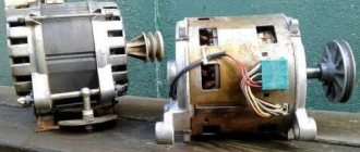
Circular saw from washing machine motor
If you have an old washing machine on your household that has exhausted its working life, you can use its parts. The motor from a washing machine can give life to a new tool.
If there is a choice, then the engine must be taken with a high power level. If there is no choice, then the engine that is available is taken as a basis.
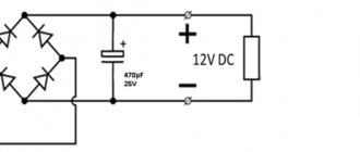
Initially, you need to prepare the motor for the future circular machine. Using an ohmmeter, the coil with the highest resistance is determined. The following are subject to verification:
- connections at the brush and commutator outputs;
- speed sensor wires.
Next, you need to connect each of the two outputs of the collector to two contacts of the coil. After connection, a test run is done and the device is connected to the power supply.
If you swap the contacts, the rotational movements will occur in the opposite direction.
You can increase the functionality of a homemade circular saw if you equip it with a device that reduces or increases the speed of rotation of the disk.
To do this, you can use a trigger from a hand-held electrical appliance or a dimmer as a basis. They are connected in the following sequence:
- one of the coil contacts is connected to the armature contact;
- the second contact is connected to mains power;
- the remaining armature output is output via a dimmer in the same way to the mains power supply.
After the motor is completely prepared, you can proceed to the further construction of the circular machine.
As a frame, it is better to take a welded metal frame, in the lower part of which the motor is fixed. The next stage involves manufacturing the motion module.
The cutting tool (disc with teeth) comes into rotation through a drive belt, which is fixed on a pressed-in smaller pulley
It is important to make notches on the pulley that will prevent the poly V-belt from sliding
To prevent the drive loop from slipping, a small protrusion is specially welded on the edge of the larger pulley.
Before starting the circular machine, it is important to check the reliability of the fastening of the disk and the motor itself. If a disc comes off during operation, it can cause serious injury, which in some cases can even be fatal.
Main stages of work
To assemble a homemade product, it is not necessary to even use a drawing, since the operation is quite simple.
How to make a circular grinder from an angle grinder - step-by-step guide:
- Assemble a miniature table from scrap materials. The legs should be of such a height that a grinder can be placed under the frame. They are secured to the stiffening ribs - small boards that are fixed along the edges of the table at a distance of approximately 125 mm from the bottom side.
- It is advisable to make the upper working surface from laminated plywood. As soon as the table top is completely ready, it must be turned face down to make a marking for installing the cutting disc (the future hole is marked along this angle grinder unit - it should be longer and wider than the cutter itself). Using a drill, you need to drill two forming points.
- Using a ruler, connect the edges of the holes by drawing two parallel lines across the entire width. Next, the basting is cut using an existing grinder. The slot for the disc is ready.
- You will need a new disk that is attached to the angle grinder. The best option for working with wood is 125 mm. The disc must have carbide teeth. The master chooses the step himself.
- At the bottom of the working surface you need to screw a bar to fix the grinder. Clamps are needed here. The device is fixed with clamps and tightened with nuts.
- You can put a new disk in the cut hole. It should be positioned so that the main part rises above the surface.
- It is advisable to make a mount for a protective visor. It can be purchased at any hardware store.
- The stop bar is made from any metal corner. It must be secured to plywood or chipboard. The length of the bar should be the same as the length of the table. Fixation is carried out at a distance of approximately 2 cm from the teeth of the disc. At the ends of the rail it is necessary to make several holes to place bolts or screws there - for reliable fixation to the table.
- Make a mount for an electrical outlet on the inside of the table. Usually fixation is carried out externally (on the stiffeners), but it can be done in a way that is more convenient for the operator.
Important! The board that will be processed must be completely placed on the tabletop, because the lumber will vibrate during operation. It will be impossible to keep it suspended, and the risk of injury will increase.
After assembly, you need to carry out the first launch and try to saw a small block.
Saw blade
Why make a machine from an angle grinder
A cutting machine is a useful and necessary thing, not only in industrial conditions, but also in the household. With this useful tool you can make precise cuts of parts and workpieces. This is achieved by securely fixing the cutting disc, into the spindle of which you can install not only abrasive wheels for cutting metal. A stationary machine can be used for cutting tiles, bricks, marble, granite and other similar materials, using special diamond-coated wheels in the design of the tool. If necessary, such a machine can be used for sawing beams, boards and other wood workpieces.
Many people who have repeatedly faced the need to make an accurate cut of a workpiece want to know how to make their own cutting machine from an angle grinder and available materials. Holding the grinder in your hands, you can also make a precise cut, but it is more difficult to do this, since you have to hold the tool exclusively with both hands. Using a homemade cutting machine, you can not only perform, but also simplify the following work:
- Cut sheet material, such as galvanizing, used for chimney insulation and other purposes
- Cut ceramic tiles and tiles - keep in mind that the cut can only be made straight
- Cut materials at different angles
- Cut a metal profile, pipe, wooden beams, boards, etc.
The manufacture of a machine from a grinder requires an appropriate approach. After all, the tool itself is very dangerous, so the slightest miscalculation can lead to the master being seriously injured. The consequences of working with an angle grinder if safety regulations are not observed are known, so first, before building a homemade product, it is worth noting the following:
- Only with the correct manufacture of a stationary cutting machine can you be confident in its reliability and safety
- If you plan to do it, then you need to calculate every step so that no disaster happens during operation.
- Using a machine is in some ways safer than using a tool while holding it in your hands. However, you need to be aware that an angle grinder is a mobile tool, and making a homemade one is already a violation of safety regulations
- For manufacturing, it is necessary to use materials of appropriate reliability, corresponding to the power and size of the main power tool.
Having dealt with the need to manufacture the machine, you can get down to business.
This is interesting!
If you can’t decide whether it’s better to buy a new machine or make it yourself, then the second option is more preferable, since the cost of a factory device will cost at least 10,000 rubles. If you make it yourself, you won’t need any expenses, since the grinder is already on the household, and the components can be found in the garage.
How to make a power button for a circular saw
To make a button, you will have to disassemble the body of the angle grinder to remove the wires. They must be connected to a switch, which is located at the manufactured base.
You can use a simpler option: tighten the start button with a clamp. In this case, the tool must be connected to the network to start working.
The simplest homemade circular
Basic operating rules and recommendations for use
Having figured out how to make a circular grinder with your own hands, it’s worth learning a few tips that you need to follow when working with the tool:
- You need to start processing materials only at the moment when the tool accelerates sufficiently.
- You should not work on a circular saw for more than 20 minutes without a break. Then the motor will not overheat.
- You need to turn on the device only if you have a protective case.
- If the disk rotation speed exceeds 10,000 rpm, then smoked parts of the wood can be seen on the cut line. Therefore, there is a risk of causing a fire. To eliminate this possibility, the rotation speed must be reduced with a voltage reduction device. The speed will be reduced.
- If, during the process of sawing wood, the grinder slows down or completely turns off, then you need to immediately remove the material being processed from the working area. If this recommendation is ignored, the angle grinder motor may burn out.
The process of converting a home tool into a machine tool is quite simple. The information provided is enough to understand how to quickly make a circular saw from an angle grinder at home.
DIY Miter Saw Guide
A crosscut is a device for cutting a product crosswise to length, and not only wooden materials, but also any other materials that can be cut by circular saws (for example, plastic). There are a sufficient number of hand-held circular saws (so-called parquet saws) on the market, with which you can:
- adjust molded products to size;
- remove excess material by cutting out blanks;
- or even make a long longitudinal cut.
But all these actions are carried out literally in weight, that is, without rigidly fixing the tool or workpiece.
In some situations, the achieved quality may be quite sufficient, but sometimes increased accuracy of the workpiece dimensions is required.
In this case, specialized cross-cutting machines, which are sold in any supermarket of construction and finishing goods, come to the rescue.
But such machines are very expensive. And besides, as a rule, the need for them never lasts long, unless you engage in carpentry professionally.
In this case, it makes sense to build a homemade miter machine using an existing hand-held circular saw.
But how to properly make a homemade miter saw from a circular saw? We will talk about this on the pages of this article.
Manufacturing details
We apply markings on the chipboard at different facing angles and screw in the hardware according to the marks.
The turning mechanism is placed on the rotational axis of the car wheel (king pin); it is supported by a bearing with a diameter of 0.15 m or more. We install a rotating semicircle with cuts.
We attach ears to the outer side of the bearing to hold them on the base with M6 screws. We put a latch with a wing on the side.
The broach is made from non-working shock absorbers. Oil is poured out of them, ventilation holes are drilled, which must be protected from small particles. So that there is no jerk at the start of the launch, it is necessary to install a soft start on the saw, which will slightly reduce the speed. We install a working bed with a cut slot for the saw.
The last stage of the activity is the installation of a protective mechanism for the disk. And we screw the guide rail to the bottom.
Our trimmer is ready to go.
Disadvantages of the unit:
- it is too noisy;
- To control cuts in wood, wood scraps are used, then the draft is set accurately, and then they cut clean.
You can make a tool from a circular saw in the same way.
A homemade workbench is the basis for convenient work
For ease of work, you should make a cross-cutting machine. It is advisable to have a mobile design if you have to move it to another place or directly to the construction site. Therefore, the frame is made collapsible, for which the tabletop is fastened to the legs using self-tapping screws.
To make a workbench, you must perform the following operations:
- Prepare the top frame. It is assembled from wooden beams measuring 40x40. Legs made of a similar material are screwed on with self-tapping screws and spacers are installed for greater stability. Or the joints are reinforced with metal corners.
- The tabletop is made from boards. Its width should be 10 cm greater than the length of the miter saw, and its length should be equal to the width multiplied by 3.
- Taking sheets of plywood (chipboard, MDF), prepare and secure improvised tables, trying to position their surface on the same level with the rotating mechanism.
- Install equipment for cutting ends.
Since it is difficult to make a high-quality rotating device at home, they take it ready-made.
Such wood trimming will be in demand in your workshop or when carrying out various construction works in which woodworking is indispensable.
If you need to make a machine with broaching, then for this you take the shock absorbers of the front struts of the car. It is preferable to a passenger car, because they are too massive for a truck. You can purchase them at any car dismantling point. Before installing shock absorbers, in order to facilitate the movement of the rod, the oil is drained and “air” holes are made in the body.
Circular cutting
When it is difficult to purchase such an instrument due to lack of finances, you can make it yourself.
For installation you will need:
- Thickened sheet of metal.
- Steel corners for pressing (use an old bed).
A welder is used to cut holes in a steel sheet, and its ends are processed with a file.
A particularly powerful electric motor is not required to use the tool; 0.9 kW is enough. It is mounted on the base with an additional spring, which performs a stabilizing task. To rotate the unit, you need to attach a handle, as a result you will achieve gradual movement of the saw. The characteristics are as follows:
- 0.2 m – diameter of the cutting disc;
- 1500 rpm – rotation speed.
This will allow you to easily process wood up to 0.07 m thick using a hand-made tool. Take care of adjustable racks and supports.
For pendulum risers, take a channel attached to a metal base. As a result, our tool will become stronger and heavier, but thanks to it, cross-cutting work will be done with ease.
You can take a three-phase electric motor (2.3 kW) and a swinging plate on hinges.
Place the belt on the motor pulley. The pendulum can be fixed to the base of the frame material. For convenient work with wood, the saw diameter must be 0.42 m, and the rotation speed must be from 2800 rpm. We cut a slot for the disk.
As you can see, it is possible not only to purchase a high-quality instrument, but also to make it yourself. Here's what we got:
Step by step guide
Let's look at the sequence of actions when converting a circular saw into a miter saw. A special feature of the “parquet” is its characteristic movement. You need to move it along the surface of the material being cut, but not vertically.
Therefore, the machine will represent itself as a base, which, firstly, will allow you to position and secure the workpiece, and secondly, it has a base with limiters along which the circular saw will move in the device (parquet).