How to connect a grinder button for replacement
Home page » For blacksmiths » How to make » How to connect a grinder button for replacement
The angle grinder is ready for use only after pressing the start button (switch).
If it fails, it will be impossible to perform a certain amount of actions using it. Repair work needs to be carried out . It is usually quite difficult to repair the button itself due to contact burnout. More often than not, a broken button is simply replaced with a new one .
Grinders: device, working methods, development prospects. Part 1
Only in Russia are manual angle grinders (angle grinders) called “grinders”.
It is unknown who came up with this name, but everyone knew that they were brought to us from Bulgaria. Although they were wrong. In the country of the “brothers”, only high-power electric drives were produced (using AEG technology), and the production itself was carried out in our USSR within the framework of cooperation (there was such a thing!) with the countries of the Council for Mutual Economic Assistance (CMEA). The angle grinder is used for cleaning, grinding and polishing various surfaces, edges and welds. They are also very effective for cutting various materials and products made of brick, stone, concrete, and metal. Due to the widespread development of diamond tools, the grinder has turned into a universal cutting machine, which is difficult to do without even in countryside conditions.
When working with an angle grinder, you should wear gloves (Photo Interskol)
The principle of operation of the grinder is visible even at the first glance at it:
- An electric motor with a current supply cable and a control unit ensures rotation of the motor rotor;
- A fan and a gear are mounted on its shaft, which meshes with a driven gear mounted on the drive spindle. It is the latter that makes the working tool rotate - a cutting disc or a grinding stone.
The main parameter of an angle grinder is the outer diameter of the grinding or cutting wheel. Based on this feature, they can be divided into one- and two-handed:
- one-handed - without a main handle with a circle diameter of 100, 115, 125 mm and a weight of up to 2.5 kg;
- two-handed - with a rear-mounted main handle and an additional handle; The diameter of the circle in this case is 125-230 mm, the weight of the machine is 2.5-6 kg.
Discs of different diameters have different permissible speeds - this information is always indicated on the label of the disc itself. The operating modes and conditions of an angle grinder are a serious test for the operation of its adjustable electric drive. It is supplied in a dust-proof design, which prevents dust from entering the windings and bearings of the motor. Such drives make it possible to:
- smoothly increasing the spindle speed to the maximum speed, allowing grinding and cutting at speeds as close as possible to the permissible ones;
- automatic stabilization of the speed mode when the forces on the tool change during operation.
This, firstly, increases the degree of use of engine power.
And secondly, it reduces the starting current by 2-3 times, allowing the electric drive to operate with a power of up to 2,500 W in electrical networks with 16 A fuses. Fitting silicate material (Photo Interskol)
The Achilles heel of the used commutator electric motors is their current collecting device, made in the form of a contact pair “commutator-brushes”. Leading manufacturers of angle grinders guarantee reliable operation of the current collector even in grinding machines, which are characterized by increased engine power, high angular speeds, and significant mechanical and thermal loads. However, carbon brushes have a lifespan of around 200 hours or more. Some models have brush self-shutdown systems that protect the motor from damage.
A characteristic feature of the working process is
the high rotation speed of the cutting wheel . It is this that provides tool speeds sufficient for cutting metals. However, even minor inhomogeneities in the structure of the disc material or uneven wear of the working surface lead to the appearance of some imbalance, causing machine vibrations. At the same time, the durability of the bearings decreases and the fatigue of the summer resident operator increases. To eliminate this phenomenon, an anti-vibration device in the form of a set of balls installed in an annular groove.
They automatically eliminate the imbalance. Another logical way to combat vibration is to insulate the handles . They are installed using special elastic-damping devices that dampen vibrations reaching the operator’s hands. In some cases, the handles themselves or their surface are made of materials with good damping properties. Combinations of the listed methods make it possible to reduce the vibration level (in terms of acceleration) below 2.5 m/s2, which, in accordance with international ISO standards, does not require restrictions on the duration of work with the machine.
When working with an angle grinder, remove any flammable materials lying nearby. Photo - Interskol
For ease of machine control, it is often possible to install handles in several positions . In order to ensure the possibility of grinding in hard-to-reach places, the body of the working head is made in the shape of a “duck’s nose”, but sometimes in a rotating position with several positions. The protective housing is an integral part of angle grinders and reliably protects the operator from mechanical damage.
In the second part of the article, we will look at the algorithm for choosing a specific model, the types of disks and working stones, and also talk about safety precautions when operating angle grinders and the prospects for the development of their designs.
Angle grinder device
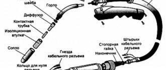
The start button is part of the design elements of the angle grinder, each of which performs its own specific task in ensuring the functioning of the power tool. The main ones, of which are the following:
- power cable for connecting the angle grinder to the network;
- stator – a stationary part of the electric drive, consisting of several excitation coils;
- anchor (rotor) – the moving part of the electric drive of the angle grinder;
- collector - part of the rotor, made in the form of insulated copper plates, providing a connection to the stator;
- brushes – provide sliding contact for transmitting current between the moving and stationary parts of the electric drive;
- gearbox - converts the rotation of the rotor created by electromagnetic interaction into spindle ;
- the design is protected from external influences by housings made of impact-resistant plastic for the electrical part and aluminum alloy for the gearbox;
- for ease of use, the grinder is equipped with a removable handle holder ;
- There are buttons on the body: an on/off button and a lock button for replacing the working tool.
Metabo W 750-125 angle grinder body, handle, shutdown and stop buttons (red and black). Photo 220Volt
Some power buttons have a soft start function, which makes the grinder more convenient and durable. There may be a speed regulator on the body, which significantly expands the functionality of the angle grinder with various materials.
Launch scheme
The design of the grinder, the energy source of which is electric current, is capable of converting it into mechanical. The interaction of all components of the angle grinder is shown in the schematic diagram for connecting its electric drive.
- Once the power cord is plugged into the outlet and the starter is turned on, electrical current is applied to one of the brushes.
- After passing through the commutator winding, the current appears on another brush , through which the stationary stator windings are supplied .
- The magnetic fields created by the stator and rotor windings interact with each other, causing rotation of the rotor mounted in bearings . Along with it, the torque occurs on the bevel gear mounted on the anchor. Another bevel gear, working in tandem with the first, rotates the spindle with the working tool of the angle grinder.
- Additional taps of the stator or rotor windings allow you to increase the functionality of the power tool by creating various control systems.
- Through the contacts of the commutator plates, signals about the rotor speed are transmitted to the tachogenerator or Hall sensor. With their help, the grinder maintains the required speed.
- To protect the angle grinder from overheating, there is a thermal protection unit. It turns off the tool if the sensor shows the maximum permissible temperature of the control surface of the angle grinder.
Scheme of operation of the grinder. Source here
Understanding the role of each of the elements included in the electrical circuit of the angle grinder allows you to correctly determine the cause of its breakdown. If the cord, button and brushes are in good condition, you should pay attention to the condition of the electric drive.
Design and principle of operation
After connecting the power cord to the mains voltage and turning on the start button, the rotor of the electric motor begins to rotate. A gear transmission at its end transmits torque to the working circle.
When rotating under load, the disk material is subjected to significant loads and if the rules for handling it were violated during storage, it can break into pieces.
To ensure safe operation of the tool and prevent accidents, perform any operations with the angle grinder only with the protective cover installed.
Design Features
Inside the impact-resistant body of the angle grinder, there is the same commutator motor that is installed in the impact drill. It consists of a stator in whose bearings the rotor rotates. Its angular speed can reach 30 thousand revolutions per minute.
The difference lies in the connection of the working body, which rotates at an angle of 90O to the axis of the angle grinder shaft. The rotating head of the gearbox ensures rotation of the torque through a helical gear transmission. It is equipped with a damper bushing that dampens mechanical shocks of the nozzle transmitted to the engine bearings.
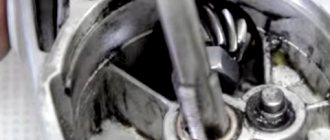
Airflow diagram
During prolonged operation with heavy loads, currents flow through the windings of the electric motor, heating the stator and rotor to high temperatures. To prevent burnout and destruction of wire insulation, a built-in forced-type cooling system is used.
Air masses are forced through the ventilation holes of the housing at the handle and are evenly driven along the electric motor, taking away excess heat from it. The heated air is discharged from the rotating head. For better heat removal, its body is made of light metal alloys.
When choosing an angle grinder for a home craftsman, pay attention to the location of the ventilation holes. During operation, they should not be covered with hands and are made with protection against sparks or dust from the material being processed.
Violation of internal air exchange can lead to a violation of the thermal balance, overheating of the windings, and breakdown of the electric motor.
Electrical diagram
In a simplified form, the connection of internal elements can be represented by the following picture.
The leads of the stator and rotor windings are connected to each other through brushes into a single serial circuit. Voltage is supplied to it through a two-pin switch.
Based on this principle, there are types of connecting electric motors with various electrical control and monitoring devices.
How to change the power button, connection process
The main symptom that the starting device is out of order is the lack of reaction from the angle grinder when the button is brought into working position. This defect can also be caused by critical wear of the commutator brushes and a break in the power cable wire.
Therefore, it is necessary to carry out diagnostics using an electrical multimeter or, in its absence, using an open circuit indicator. To do this, it is imperative to remove the plastic case that protects the electrical part of the angle grinder in order to get to the button contacts, the connection point of the power cable and the ability to check the operation of the brushes.
If the contacts are not called, proceed to replace it. The entire process, including diagnostics, is described in the video below. It should be noted that the button that failed here is being replaced with a similar one in design. In passing, the condition of the brush assembly of the angle grinder is assessed, and recommendations are given on a possible simpler replacement of the brushes.
How to connect directly without a button
If an urgent need arises when leaving the start button, you can supply power directly to the two network wires extending from it into the angle grinder. In this case, the capacitor, which has the main function as a spark arrester when the brushes operate, will also not be involved in the work. And this despite the fact that when the plug is turned on/off from the socket, transient processes will intensify and increase the tendency to form sparks.
an electronic soft start circuit works together with the button , which eliminates a sharp increase in current during startup and makes working with the angle grinder convenient and safe. It is clear that in this mode of operation the angle grinder will quickly fail . It is better to replace or, if possible, repair the start button.
The purpose of each power supply element of the angle grinder 125
The grinder circuit includes several elements that ensure its smooth operation.
Purpose of elements for power supply:
- Anchor. This part facilitates the movement of the abrasive wheel for cutting metal products and workpieces. It is necessary to create greater speed in relation to the disks to ensure their rotational movements. And, accordingly, at a higher anchor speed, the power indicators of the tool are higher.
- Collector. This is a platform located on an anchor to which all power lines are connected. Its main function is to transmit signals through the windings to the motor and control unit so that the elements correctly perceive this information. The element immediately catches your eye when you remove the cover from the case, as it has a polished surface and its dimensions are quite large.
- Electric brushes. The purpose of these elements is to supply electric current to the cable. During normal operating placement, a glow will be observed emanating from them through the opening provided for ventilation. If it is noted that this is absent, is weak or almost unnoticeable, then this is an indicator that there is a problem with the electric brushes.
- Gearbox. The main structural part for the electrical circuit and for the entire technical device as a whole. Its function is to transfer electricity from the armature to the abrasive disc. This ensures rotation, which creates work. In fact, only the gearbox helps to increase the speed and power characteristics of angle grinders.
- Stator. This is the most complex knot that complements the grinder device. It is in it that the windings of both the armature and the rotor are located, which are the primary mechanisms that provide movement. The windings of the stator coil are clearly calculated until the last turn. If this element fails, it is unlikely that an inexperienced worker will be able to restore the winding. This happens, but in exceptional cases. It is best to contact a specialized workshop regarding stator rewinding.
Read also: How to check battery performance with a multimeter
How to replace the retainer
There is another button on the gearbox housing of the angle grinder, with which you can quickly change a worn or broken working tool. Locking the spindle by pressing this device against rotation makes it easy to replace. It also fails due to improper operation of the grinder (pressing a button while the spindle is rotating) or when changing a tightly clamped working tool. You can read in detail how to replace the lock in the description at the link “Bulgarian stopper button”.
I ask for theoretical assistance in repairing an angle grinder (electrician)
Question about repairing an angle grinder. Help! Bulgarian Hertz (sort of) power 2050W
I had to work. It was hot. In short, something puffed. I took it apart, and there the soft start unit (with three wires) turned black. I opened it a little, and there a certain element very reminiscent of a transistor was blown up.
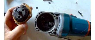
The angle grinder was disassembled piece by piece, cleaned, purged. Visually, the winding was intact, both on the shaft and on the stationary part. brushes and commutator are in more or less condition
I found a similar one on the market, but it was used (they gave it away for free and they said it had to be working), the diagram is drawn on the case (there are abc wires, and how to connect) what and where. Connected. Assembled. I press the button and it explodes. The block explodes again. Why? what else can you see? Could there be a turn short circuit somewhere (not visually visible) and that’s why?
Maybe you can immediately apply phase and zero to the brushes, that is, directly? but there is a small capacitor installed near the button. For what?
Electrical Diagram of the Grinder
89243 views
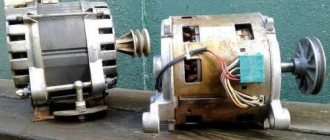
In the last article I told you how to connect and start a 380 Volt motor in a single-phase 220 V electrical network. Now I will talk about how to connect a single-phase electric motor from a broken washing machine, vacuum cleaner, etc. It can be successfully used for other purposes in household, for example, to drive a sharpener, polishing machine, lawn mower, etc.
Connection diagram for a 220 Volt commutator motor
Electric drills, rotary hammers, grinders and some models of automatic washing machines use a synchronous commutator motor. It successfully starts and works in single-phase networks without unnecessary starting devices.
In order to
connect a commutator electric motor , it is necessary to connect the two ends No. 2 and No. 3 with a jumper, one coming from the armature, and the other from the stator.
And connect the remaining 2 ends to a 220 Volt power supply. Remember that when connecting a commutator electric motor without an electronics unit, it will only operate at maximum speed, and when starting there will be a strong jerk, high starting current, and sparking on the commutator.
The motor may also have a 2-speed motor, then the 3rd end will come out of the stator from half of its winding. When connected to it, the shaft rotation speed will decrease, but this increases the risk of insulation failure when starting the motor.
To change the direction of rotation, it is necessary to swap the ends of the stator or armature connection.
Connection diagrams for single-phase asynchronous electric motors
If single-phase electric motors had only one winding in the stator, then the electromagnetic field inside it would be pulsating rather than rotating. And the launch would occur only after unwinding the shaft by hand. Therefore, to independently start asynchronous motors, an auxiliary or starting winding is added, in which the phase is shifted by 90 degrees using a capacitor or inductance. The starting winding pushes the rotor of the electric motor at the moment of switching on. The main connection diagrams are shown in the figure.
The first two circuits are designed to connect the starting winding while the motor is starting, but not more than 3 seconds in duration. To do this, use a relay or a start button, which must be pressed and held until the engine starts.
Electrical tool repair. Rewinding the stator (excitation coils) part 1.
The cause of a malfunction of the commutator motor is detected by a measuring device, using the example of such devices as:
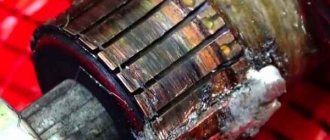
So, let’s say that the burnout of the stator windings (Fig. 3) is usually caused by the completion of the general overheating of the electric motor. In this case, the insulation of the wires in the stator winding is broken and the winding itself can short-circuit to the frame body. To establish such a probable cause of malfunction, one probe tip of the device is connected to the output end of the stator winding wire, the second tip of the probe is connected to the stator frame housing.
To check the rotor winding, the probes of the device must be connected to the lamellas (plates) of the collector (Fig. 4).
This matter remains for our client for now. Look behind the heading.
please tell me the cross-section of the wire of the stator winding of the angle grinder Kolner 580 wt. Number of turns 167
Hello Damir. There is no need to carry out calculations here. It is necessary to take a piece of wire from the stator winding of the angle grinder and measure the cross-section of the copper wire with a caliper \lathe measuring equipment\ or contact a dealer consultant with this piece of wire when purchasing the wire. It is better that the rewinding of the electric motor stator is done by a corresponding specialist, because the winding resistance is also taken into account.
Hello, gentlemen electricians! Please tell me why the electric motor of an angle grinder can heat up when rotating idle for a period of 2-3 minutes after switching on to a cool one after changing the rotor. At first, while working with a diamond disc on the newest grinder, it was overheated by stopping the disc at full rotation of the rotor. We disassembled and checked the rotor - there was a break in the circuit on the commutator (two dark lamellas). It’s not just discs or cassettes that were not inspected. We installed a new rotor and it began to heat up without load.
Electrical diagram of an angle grinder with a capacitor
After a certain period of use, the grinder is characterized by such breakdowns as wear of the graphite brushes, burnout of the windings
stator no further. Naturally, wear itself is not excluded, not in terms of mechanics. To fully familiarize yourself with the topic: “How to repair an angle grinder,” let’s look at the electrical circuit of a commutator AC motor, since such an electric motor is installed in the angle grinder.
AC brushed motor circuit diagram
The diagram (Fig. 1) shows the electrical connections of the stator and rotor windings of non-graphite brushes. Graphite brushes in the electric motor are installed in brush holders. The brushes are in contact with the commutator lamellas. Some ends of the stator windings are connected to an external energy source. The other ends of the stator windings are connected to graphite brushes, electrical
the circuit is closed on the rotor windings.
The regulator is connected by wires to the commutator motor circuit in series. The connection diagram must be indicated on the regulator body itself, or in the grinder’s operating manual.
The device of the grinder
According to the design of the grinder
, our indicated in the figure does not need any specific explanation. Using driven non-driving bevel gears, rotation is transmitted from the electric motor to the gearbox shaft.
Commutator motor malfunctions
How to replace graphite brushes
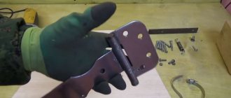
Based on practical data, it has been established that the most vulnerable part in a technical device, including the 1100E, is graphite brushes. Their service life is no more than 2 years. To replace old brushes with new ones, you do not need to have experience. Such manipulation will not be difficult even for an inexperienced person. To examine the condition of the brushes, you need to open the tool body, including the 1100E.
In this case, the device must be de-energized, and the brush holders installed on the commutator must be carefully moved to the side. The use of a screwdriver for this operation is mandatory.
If the technical device is manufactured by a specialized company, then the brushes can be held in place using a spring. To remove the brush, you need to press these springs with a screwdriver. If the manufacturer of the tool is China, then in these places there are plugs, which are also removed with a screwdriver, and only after that the brush can be easily removed. To determine which brush you need to purchase, it is recommended to take the removed part with you to the store and, accordingly, select a similar one there, strictly according to the given parameters. When inserting a brush into an angle grinder, these actions must be performed smoothly and slowly. It is important to note that it does not cling to anything and is installed evenly in the socket.
Read also: How to make a tire changing machine with your own hands
In the same way as the installation of the first brush, you can install the second one. After this, you need to check the location of the wires in the technical device so that they are not pinched anywhere. Now you can close the case and turn on the machine in test mode.
Any power tool with a commutator motor (grinder drills and others) has a rather large capacitor (0.2 - 0.5 mF). Even a cheap Chinese instrument contains this element. Searching for an answer on the Internet yielded nothing except that it was needed “to reduce the interference created by sparking brushes.” I think its role is to dampen the sparking of the brushes, reducing the heating of the commutator and brush assembly. And a decrease in sparking leads to a decrease in interference. Who knows the exact answer?
This capacitor is from a Chinese grinder with a power of 600 Watt.
The capacitor is installed in devices with a commutator motor precisely to dampen high-frequency interference that occurs during engine operation. The resistance of a capacitor is inversely proportional to the frequency of the alternating current flowing through it. For alternating current with a frequency of 50 Hz, the resistance of a capacitor with a small capacitance is so high that the current flowing through it can be neglected.
Another thing is high-frequency interference from collector sparking. For them, the capacitor resistance is low. And the current with the interference frequency mainly flows through the capacitor without entering the power supply.
In more expensive devices, an inductance is also placed in the power supply circuit break, the resistance of which for RF current is high. Together, the capacitor and inductance(s) make up a classic high-pass filter.
After a certain period of use, the grinder is characterized by such breakdowns as wear of the graphite brushes, burnout of the stator windings, and so on. Of course, wear itself also occurs in terms of mechanics. To fully familiarize yourself with the topic: “How to repair an angle grinder,” let’s look at the electrical circuit of a commutator AC motor, since just such an electric motor is installed in an angle grinder.